
Rotary piston meters DN 15 (½") with single-pointer dial type 01, without accessories
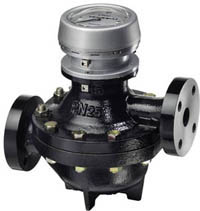
Rotary piston meters DN 25 (1") with single-pointer dial type 01
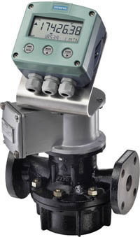
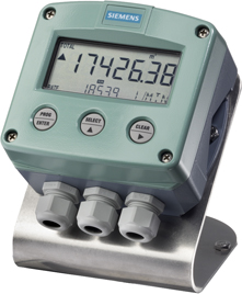
Rotary piston meters with electric flow register in compact form
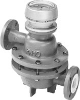
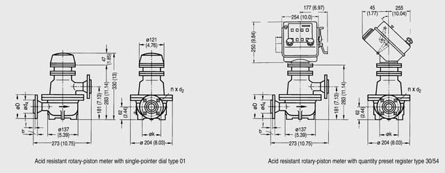
Acid-resistant rotary piston meters DN 25 (1") with single-pointer dial type 01, without accessories
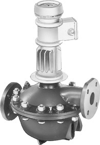
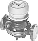
Rotary piston meters DN 50 (2") with mech. single-pointer dial, type 01, with accessories (here: cooling attachment and pulser)
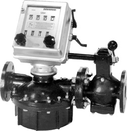
Automatic batchmeters DN 50 (2"), with rotary piston meter, quantity preset register and shut-off valve
| | | | |||
Version | Rotary piston meters | Acid meters | |||
Nominal diameter | DN 15 | DN 25 | DN 50 | DN 80 | DN 25 |
Order No. | 7MR10..-... | 7MR11..-... | 7MR14..-... | 7MR16..-... | 7MR111.-... |
Pressure level | |||||
PN 6 | • | ||||
PN 10 | • | • | |||
PN 16 | • | • | |||
PN 25 | • | • | • | • | |
PN 40 | • | • | • | ||
PN 63 | • | • | |||
Flow variables | |||||
Max. 20 l/min | • | ||||
Max. 100 l/min | • | • | |||
Max. 500 l/min | • | ||||
Max. 1,000 l/min | • | ||||
Flange standards | |||||
Drilled acc. to EN | • | • | • | • | • |
Drilled acc. to ASME | • | • | • | • | • |
With raised faces | • | • | • | • | • |
Approvals | |||||
Custody transfer | • | • | • | ||
Material acceptance test to EN 10204-3.1 | • | • | • | • | |
ATEX | In preparation | ||||
Piston materials | |||||
Carbon | • | • | • | • | • |
Cast iron | • | • | • | • | |
Ni-resist | • | • | • | ||
Hard rubber | • | • | • | • | |
PTFE 40 °C | • | • | • | ||
PTFE 90 °C | • | • | • | ||
CrNiMo steel with carbon contact surface | • | ||||
CrNiMo steel with PTFE contact surface | • | ||||
PCTFE | • | • | • | • | |
Designs | |||||
Mechanical single-pointer dial | • | • | • | • | • |
Mechanical double-pointer dial | • | • | • | • | • |
As automatic batchmeter (incl. shut-off valve) | • | • | |||
With electronic flow register | • | • | • | • | • |
Remote or compact installation | • | • | • | • | • |
For use in closed liquid circuits at pressures up to PN 63 (MWP 914 psi) and liquid temperatures up to 300 °C (572 °F).
A prerequisite for exact measurements is that the liquid is homogeneous without coarse solid impurities or gas inclusions.
Rotary-piston meters are mainly used in the petroleum industry, the raw material industries, the chemical industry, the foodstuffs and beverage industries and in power stations and district heating stations:
The basic version (meter mechanism and register) is used primarily for metering applications in the production, distribution and consumption of liquids.
They complement one another with respect to the flow rate ranges but have particular advantages for specific applications.
Rotary-piston meters are approved for custody transfer in the European Union and in many other countries.
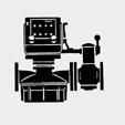
Rotary-piston meter | Automatic batchmeter | ||||||||||||||
|---|---|---|---|---|---|---|---|---|---|---|---|---|---|---|---|
Industrial version DN 25 (1") ... DN 80 (3") | Industrial version | Acid-resistant version | Rotary-piston meter with mechanical shut-off valve and quantity preset register | ||||||||||||
 |  | 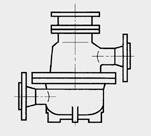 | 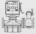 | ||||||||||||
For industrial liquids such as: alcohols, bitumen, dispersions, paints, greases, liquid gases, adhesives, lacquers, alkalis, solvents, mineral oils, acids etc. | For industrial liquids such as: alcohols, bitumen, dispersions, paints, greases, liquid gases, adhesives, lacquers, alkalis, solvents, mineral oils, acids etc. | For particularly corrosive liquids such as: phosphoric acid, hydrochloric acid, dilute sulfuric acid, etc. | For industrial liquids such as: alcohols, bitumen, dispersions, paints, greases, liquid gases, adhesives, lacquers, alkalis, solvents, mineral oils, acids etc. | ||||||||||||
Rated flow | Rated diameter DN | Order-No. | page | Rated flow | Rated diameter DN | Order-No. | page | Rated flow | Rated diameter DN | Order-No. | page | Rated flow | Rated diameter DN | Order-No. | page |
l/min (USgpm) | mm (inches) | l/min (USgpm) | mm (inches) | l/min (USgpm) | mm (inches) | l/min (USgpm) | mm (inches) | ||||||||
20 (5.3) | 15 (½") | 7MR1020 7MR1030 | |||||||||||||
100 (26.4) | 25 (1") | 7MR1110 | 100 (26.4) | 25 (1") | 7MR1120 7MR1130 7MR1140 | 100 (26) | 25 (1) | 7MR1111 | 100 (26) | 25 (1) | 7MR1112 7MR1113 | ||||
500 (132) | 50 (2") | 7MR1410 | 500 (132) | 50 (2") | 7MR1420 7MR1430 7MR1440 | 500 (132) | 50 (2") | 7MR1412 7MR1413 | |||||||
1000 (264) | 80 (3") | 7MR1610 | 1000 (264) | 80 (3") | 7MR1620 7MR1630 | ||||||||||
Rotary-piston meters are characterized by:
Nominal diameter (DN), nominal pressure (PN) and permissible flow rates q for rotary-piston meters and automatic batchmeters | |||||||||||||
|---|---|---|---|---|---|---|---|---|---|---|---|---|---|
Version | DN | PN | Rated flow | Permissible flow rate | |||||||||
With | Min. 1) in continuous operation 2) | Max. in intermittent operation 3)4) | Max. in | ||||||||||
mm | (inch) | bar | (psi) | l/min | (USgpm) | mPa·s (cp) | l/min | (USgpm) | l/min | (USgpm) | l/min | (USgpm) | |
Rotary-piston meters for industrial use | |||||||||||||
 | 15 5) | (½) 5) | 25 | (363) | 20 | (5.3) | ≤ 1 | 1,5 | (0.26) | 10 6) | (5.3) | 10 | (2.6) |
25 | (1) | 10 | (145) | 100 | (26.4) | 0,3 | 12 | (3.2) | 100 | (26) | 80 | (13) | |
50 | (2) | 6 | (87) | 500 | (132) | 0,3 | 40 | (11) | 500 | (106) | 350 | (44) | |
80 | (3) | 6 8) | (58) | 1000 | (264) | 0,3 | 60 | (16) | 1000 | (211) | 700 | (93) | |
Rotary-piston meter of acid-resistant design | |||||||||||||
 | 25 | (1) | 10 | (145) | 100 | (26.4) | 0,6 | 10 | (2.6) | 100 | (26) | 50 | (13) |
Automatic batchmeter (rotary-piston meter with quantity preset register and mechanical shut-off valve) | |||||||||||||
 | 25 | (1) | 10 | (145) | 100 | (26.4) | 0,3 | 12 | (3.2) | 100 | (26) | – | – |
50 | (2) | 6 | (87) | 500 | 132 | 0,3 | 40 | (11) | 500 | (106) | – | – | |
1) For metal rotary-pistons: increase by a factor of 2, for PCTFE and PTFE/graphite filling rotary-pistons: increase by a factor of 3.
2) Continuous operation: over 8 hours a day.
3) For metal pistons: Reduce by a factor ≈ 0.8 to extend service life
4) Intermittent operation: up to 8 hours a day
5) Note: When using pistons made of carbon, there is higher risk of breakage in case of liquid hammers
6) When using pistons made of carbon
7) Flow rates for higher viscosities on request; we have experience with ranges up to 350000 mPa s (cp)
8) Values in brackets apply to casing made of CrNiMo steel
9) Max. permissible viscosity for exact closing of the shut-off valve and for exact dispensing; viscosities up to around 4000 mPa s (cp) possible
Note:
In order to extend the service life of the pulse sensor, rotary-piston meters with current and/or pulse output (without intermediate gear) should only be operated at max. 60 % of the permissible flow.
Piston material | Version | Permissible liquid temperature | Max. perm. dyn. viscosity | Order No. code | |
|---|---|---|---|---|---|
°C | °F | mPa·s (cp) | |||
Carbon | -10 ... 300 | 14 ... 572 | 25 | K | |
Cast iron (mat. No. GG 25) |
| -10 ... 300 | 14 ... 572 | E | |
Ni-Resist (mat. No. 0.6660) |
| -10 ... 300 | 14 ... 572 | N | |
Hard rubber |
| -10 ... 40 1) | 14 ... 104 1) | 50 | G |
PTFE/graphite filling |
| 0 ... 40 2) | 32 ... 104 2) | 120 | F |
PCTFE |
| -10 ... +40 2) | 14 ... 104 2) | 120 | H |
CrNi steel with carbon contact surface (only DN 25 (1“)) | Collar piston | -10 ... +200 | 14 ... 392 | > 10 | S |
1) For 120 min max. 65 °C (149 °F); for 20 min max. 90 °C (194 °F), e.g. for cleaning purposes
2) Error limit max. 1 %, at 90°C (194 °F) max. 2 %.
Other technical specifications | |
|---|---|
Materials and max. permissible liquid temperatures | |
Housing (also lining with acid-resistant meters) and measuring chamber | Temperature range |
| -30 ... +300 °C (-22 ... +572 °F) |
| -20 ... +80 °C (-4 ... +176 °F) |
Error limits | |
Error limits | Between 0.2 % and 0.5 % of the correct value (depending on the metered fluid, the measuring range and the relevant calibration regulations), except for rotary-piston meters DN 15 (½“) and acid-resistant meters with PCTFE pistons; where 1 % of the actual value applies. |
Reproducibility | Within 0.05 % |
Controllability | In steps from 0.01 % |
Rated loss | Max. permissible 3 bar (43.5 psi), max. 0.5 bar (7.25 psi) for acid resistant meters |
Transmission from wet to dry space | Gland-free, using permanent magnet coupling |
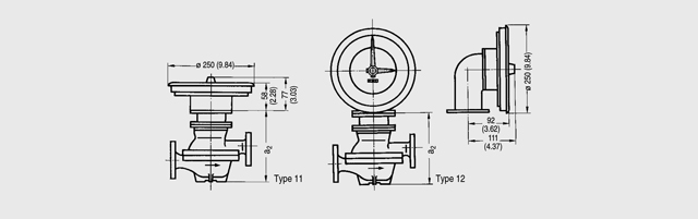
Installation position (axis of meter mechanism) | |
| |
| Any |
| Vertical |
| |
| Any |
| Meter axis vertical |
Special inlet and outlet pipe sections | Not necessary |
Pipe connection | Flange drilled to EN 1092-01 |
Filter size (mesh width) | 0.8 mm (0.031 inch) for rotary-piston meters |
The material combinations which can be supplied are listed in the Ordering data.
The maximum permissible liquid temperature is determined by the “weakest link” in the particular combination (the PCTFE rotary-piston or the gasket, for example, in a meter made of CrNiMo steel).
Automatic batchmeter
With this meter, the maximum permissible liquid temperature is also limited by the operation and design of the shut-off valve.
The following are permissible for valves with maintenance free
Models for higher liquid temperatures on request. The installation of cooling attachments also necessitates a corresponding increase in length of the mechanical shut-off valve.
The following restriction applies to the automatic batchmeters because of the higher flow resistance through the associated shut-off valve:
If the dynamic viscosity is greater than 60 mPa s (cp), constructional details of the shut-off valve cone must be changed.
Also, no filter is installed if the dynamic viscosity exceeds 800 mPa s (cp).

Metering mechanism of a rotary piston meter DN 25/PN 10 (1“/MWP 145 psi) (industrial model)
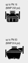
To achieve rated pressure levels PN 25, PN 40 and PN 63 (MWP 363, 580 and 914 psi) - the measuring chamber is installed in the housing. The meters for rated pressures PN 4, PN 6, PN 10 and PN 16 (MWP 58, 87, 145 and 232 psi) have a measuring chamber machined to the lower part of the case.
All components of the meters are made of wear-resistant materials. Several materials are available for the parts which come into contact with the metered liquid (see Selection and Ordering data). The most suitable combination can be selected taking into account the corrosion resistance with respect to the liquid to be measured as well as the running characteristics and the permissible temperatures; the material recommendations aid selection.
Mechanical displays | Digital displays | |||||
|---|---|---|---|---|---|---|
Compact design | Remote design | Compact design | ||||
Without pulse and current output | With pulse and current output | With pulse and current output Incl. protective cover | With pulse and current output Incl. mounting bracket | |||
Registers | ||||||
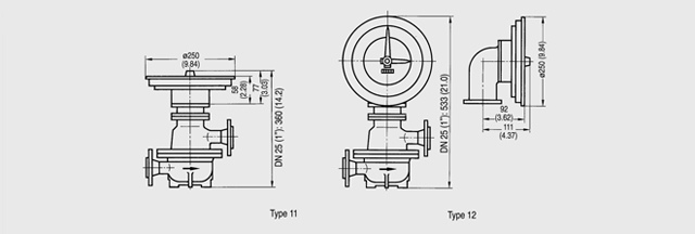
Single-pointer dial, type 01 | 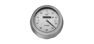 | • | • | • | ||
Double-pointer dial, types 11 and 12 | 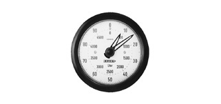 | • | • | • | ||
Quantity preset register | 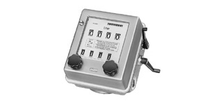 | • | • | • | ||
SITRANS F RA110 electric flow registers (7MV1070-... | ||||||
| 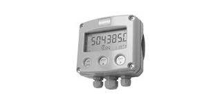 | • | ||||
|  | • | ||||
Protective cover | ||||||
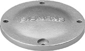 | • | |||||
Pulser | ||||||
10 pulses/revolution, | 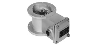 | • | • | |||
10 pulses/value per revolution, | • | |||||
Intermediate gear | ||||||
 | • | • | • | |||
Pulser | ||||||
10 pulses/measuring chamber volumes, | | • | ||||
Cooling attachment | ||||||
Up to 80 °C: None | 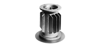 | • | • | • | • | • |
Up to 180 °C: One | ||||||
Up to 260 °C: Two | ||||||
Rotary piston meters and automatic batchmeters | ||||||
Rotary piston meters DN 15: 7MR10..-... DN 25: 7MR11..-... DN 25: 7MR1111-... DN 50: 7MR14..-... DN 80: 7MR16..-... Automatic batchmeters DN 25: 7MR111.-... DN 50: 7MR141.-... | 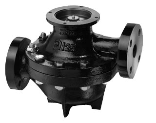 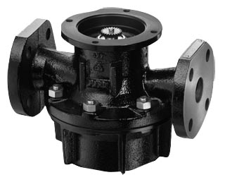 | • | • | • | • | • |
Measuring chamber volumes: DN 15 (1/2“): 0.033l (0.0087 USgpm) DN 25 (1“): 0.179l (0.0473 USgpm) DN 50 (2“): 1.5 l (0.317 USgpm) DN 80 (3“): 4.32 l (1.14 USgpm) | ||||||
When metering flowing liquids, either the volume V is recorded over a given time t or the momentary flow rate q is determined.
The relationship between these variables is V = q · t.
In accordance with these two measuring principles, a differentiation is made between:
Rotary piston meters are direct volumetric meters. They operate according to the positive displacement principle. Their operation is based on the continuous limitation of defined portions of the volumetric flow in the mechanism by continuous filling and emptying of the measurement space. This consists of the walls of the measuring chamber and the moving part, i.e. the rotary piston.
The rotary piston is driven by the pressure difference in the metered liquid between the inlet and outlet. The meters are basically purely mechanical devices operating without a power supply.
The rotary piston (6) which has a double T-shaped cross section is guided by its gudgeon or guide pin (3) in an annular space in the base of the measuring chamber and also by its slot on the barrier (1).
The inlet port (2) and outlet port (7) are located on either side of the barrier. They are continuously sealed by the rotary piston and the barrier.
The incoming liquid fills the sickle-shaped spaces, attempts to enlarge them and thus turns the piston until the volumes V1 und V2 are reached in succession. With the further movement of the piston, this filled space is connected to the outlet and emptied. Since the two sickle-shaped spaces – the inner and outer – are displaced with respect to one another, no deadpoint occurs during the movement of the piston. The piston moves continuously according to the flow of the metered liquid.
The rotary movement of the piston guide-pin is picked up by a drive member and transmitted via a gland-free (industrial design only) permanent magnetic coupling to the register. One revolution of the piston pin corresponds to the passage of the capacity of the measuring chamber (V1+V2) through the meter. A gear unit converts the revolutions into a decimal value of e.g. 10 l, 100 l, 1 m3 or gallons.
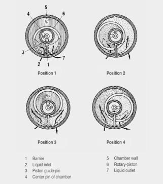
Measuring process in the rotary piston meter
When planning a liquid metering system, it is first necessary to clarify the operational and measuring requirements:
Intended use of the system
This determines the operating mode, which can be continuous or intermittent.
The type of volumetric meter to be used and the design of the measuring system also depends on the intended use.
Although the numerical ranges must be greater in systems for continuous measurements, the registers for this mode of operation can be simpler.
The system design also becomes much simpler for continuous operation. For example, there is no need to consider the problems of quantity limitation as in the case of intermittent operation. In the latter type of systems, the reliable separation of the liquid remaining in the metering system from the metered quantity – the quantity limitation – is one of the most important conditions for the accuracy of the system.
Distances between storage tanks, metering point and quantity limitation point
The distances are mostly determined by fixed local conditions. In this case it is often necessary to find a means of reaching a practical compromise between system engineering and operational necessities.
A liquid metering system can consist of:
Like the filter and gas separator, the meter should also be installed in the pipe such that it always remains filled with liquid. This helps prevent errors in measurement and corrosion due to the ingress of air.
All the meters, registers and accessories are designed on a modular basis, and therefore all have the same connecting flanges.
Flow shutoff
The flow of liquid is interrupted by this equipment – valve, gate, tap, etc. – when the intended quantity has been delivered.
In order to prevent harmful pressure surges (water hammer) and large overshoot quantities, the flow should be throttled continuously or in several stages before the final shut-off. Our quantity preset register with mechanical shut-off valve operates with four shut-off stages (see "Registers and quantity preset registers").
The SITRANS F RA110 current or pulse output can also be used to control electric shut-off valves.
Quantity limitation
When the metered liquid has flowed through the metering system, it passes either into the process plant or into a vessel for further transport. The transition point from the metering system is significant from a measuring viewpoint and is referred to as the quantity limitation. If exact measurements are to be achieved, the metering system – from the gas separator to the quantity limitation – must always be filled with measurement material. A differentiation is made between two modes of operation depending on the location of the quantity preset limitation:
When planning systems for batch operations it is important to take into account the "minimum delivery quantity" that can be measured and indicated with sufficient accuracy by the selected register. The regulations for metering systems for custody transfer can serve as a guideline:
The minimum delivery quantity is the smallest quantity which can be measured in one operation with permissible error limit.
It is also dependent on the value per revolution of the fastest element of the register. The value per revolution corresponds to that quantity which is indicated by a full revolution of this element (pointer or drum).
The minimum delivery quantities generally have the following relationships to the values per revolution:
Certain values per revolution or certain values of the minimum delivery quantity are assigned to each nominal diameter of the individual meter types. These values have been selected such that they almost always represent the best solutions to the metering problems. Should it be found during the planning of a system that the minimum delivery quantity attainable with the value per revolution stated in the catalogue does not correspond to the operational requirements, please contact us.
Viscosity in the CGS and SI systems
Viscosity is a measure of the internal friction of a liquid. A differentiation is made between dynamic and kinematic viscosity. Dynamic viscosity is the decisive factor for the use of volumetric meters. Common viscometers generally determine the kinematic viscosity. The dynamic viscosity can be calculated from it as follows:
Dynamic viscosity | = kinematic viscosity | x density |
|---|---|---|
1 mPa·s | = 1 mm²/s | x 1 g/cm³ |
Conventional viscosity units
In practice, calculations were frequently carried out with common engineering units based on the flow times of liquids from standard orifices. The most common units of this kind were
The figure "Conversion into common engineering units" shows these common units in comparison to the mm²/s values of the kinematic viscosity of the CGS system.
Note: The temperature to which the value refers must be specified with each viscosity value.
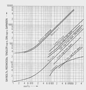
Conversion of the kinematic viscosity-unit mm²/s into other units
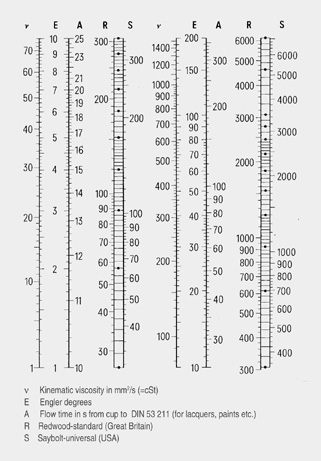
Conversion of the kinematic viscosity unit into common engineering units (water at 17 °C (68.2 °F) has a dynamic viscosity =1.09 mPa·s (cp)
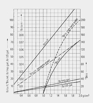
Conversion of the density unit g/cm³ into other units
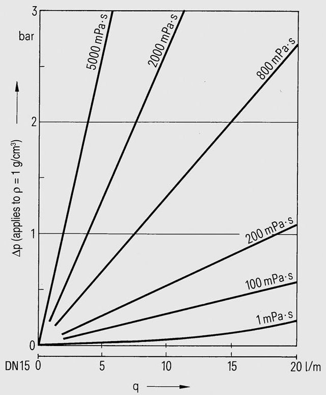
Pressure loss depending on the flow and viscosity of the measured liquid in a rotary-piston meter DN 15 (½")
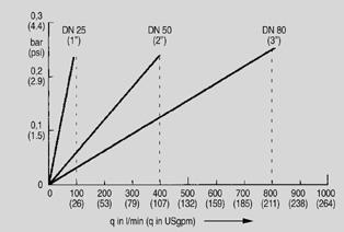
Pressure loss p for liquid gas with 0.25 mPa·s (cp), approx. 16 °C (60.8 °F) and PN 16 (MWP 232 psi); values for liquid gas authorized by the German calibration authorities: 100, 400 and 800 I/min (26.4, 106 and 211 USgpm))
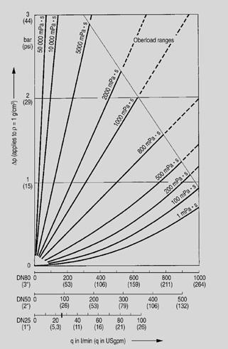
Operating ranges for rotary-piston meters DN 25 (1"), 50 (2") and 80 (3"); pressure loss depending on the flow and viscosity of the measured liquid.
Caution!
The following limitation applies to the automatic batchmeter because of the higher flow resistance through the associated shut-off valve:
Several materials are available for those parts of the rotary-piston meters which come into contact with metered liquid. These materials must be combined with due regard to the corrosion resistance against the metered liquid.
The table "Recommended materials" shows combinations of materials for a number of liquids.
In order to keep the summary as simple as possible, only the minimum version is listed in each case. However, higher quality materials can also be used for metered liquids. If this is required by the customer, e.g. for multipurpose use of the meter, please inquire in case of doubt.
The data is based for the greatest part on our many years of experience. Because of the complexity of the corrosion problem, however, the data should only be considered as recommendations. It does not constitute a guarantee.
Restrictions of the application range for the recommended materials imposed by the casing gasket | ||||||||
|---|---|---|---|---|---|---|---|---|
Rotary-piston meter | Casing gasket | Permissible temperature range | ||||||
Order-No. | Normal size (DIN) | Rated pressure (DIN) | Nominal diameter (ASME) | ANSI B16.5 | Type | Material | °C | °F |
7MR1020 | DN 15 | PN 25 | (½") | (300 … 600) | Flat gasket | AFM 34 2) | -10 ... +260, for a short time up to 300 | (14 ... 482, for a short time up to 572) |
7MR1110 | DN 25 | PN 10/PN 16 | (1") | (150) | ||||
7MR1120 | PN 25 | (300 … 600) | ||||||
7MR1140 | PN 63 | (900 … 1500) | ||||||
7MR1410 | DN 50 | PN 6/PN 10 | (2") | (150) | ||||
7MR1420 | PN 25 | (300 … 600) | ||||||
7MR1440 | PN 63 | (900 … 1500) | ||||||
7MR1610 | DN 80 | PN 4/PN 6 | (3") | (150) | ||||
7MR1620 | PN 25 | (300 … 600) | ||||||
7MR1130 | DN 25 | PN 40 | (1") | (300 … 600) | O-Ring | FPM 3) | -10 … +260 | (14 … 500) |
7MR1130 | O-Ring | FEP-FPM 4) | -10 … +200 | (14 … 392) | ||||
7MR1430 | DN 50 | PN 40 | (2") | (300 … 600) | O-Ring | FPM 3) | -10 … +260 | (14 … 500) |
7MR1430 | O-Ring | FEP-FPM 4) | -10 … +200 | (14 … 392) | ||||
7MR1630 | DN 80 | PN 40 | (3") | (300 … 600) | O-Ring | FPM 3) | -10 … +260 | (14 … 500) |
7MR1630 | O-Ring | FEP-FPM 4) | -10 … +200 | (14 … 392) | ||||
2) AFM 34: Aramide fibers with inorganic fillers and synthetic elastomers
3) FPM: Fluorine rubber (Viton)
4) FEP-FPM: Fluorine rubber (FEP-Viton), encased in tetrafluoroethylene-hexafluoropropylene
1) The flanges are drilled according to ASME B16.5. The pressure data according to DIN are maximum permissible pressures up to approx. 100 °C (212 °F). The maximum permissible pressure is reduced at higher temperatures. When ordering, the data of the ANSI pressure classification must be specified in plain text.
Instructions for using the following table "Recommended materials"
The recommended material combinations are marked with "•". If several materials are listed for one metered liquid, these are alternatives for the casing and the measuring chambers since possible limitations apply to the minimum version (see footnotes).
In case of several recommendations for rotary-pistons, the running characteristics and the permissible temperatures have been taken into account. No preference is expressed, the choice should be made according to customer requirements.
The data in the summary generally applies to a liquid temperature of 20 °C (68 °F). with the exception of substances which can only be metered, when heated, e.g. bitumen or cocoa paste.
The word "solution" always denotes an aqueous solution.
Materials | Casing and measuring chamber | Rotary piston | Casing gasket | |||||||||
|---|---|---|---|---|---|---|---|---|---|---|---|---|
Liquids | Cast iron | CrNiMo | with | Cast iron | Ni-resist | Carbon | Hard rubber up to | PCTFE | PTFE/graphite up to | PN 4/6/10/25/63 AFM 34 | PN | 40 |
FPM | FEP-FPM | |||||||||||
Acetaldehyde | • | • | • | • | • | |||||||
Acetone | • 1) | • | • | • | • | |||||||
Acrylonitrile | • | • | • | • | ||||||||
Aluminum sulfate solution | • | • | • | • | • | • | ||||||
Formic acid | • | • | • | |||||||||
Ammonia solution | ||||||||||||
| • | • | • | • | • | • | ||||||
| • | • | • | • | ||||||||
Ammonium chloride solution | • | • | • | • | • | • | ||||||
Amyl acetate | • | • | • | • | ||||||||
Amyl alcohol | • | • | • | • | • | • | • | |||||
Aniline | • 1) | • | • | • | • | |||||||
Barium chloride solution | • | • | • | • | • | • | • | |||||
Benzaldehyde | • 1) | • | • | • | • | |||||||
Benzene | • 1) | • | • | • | • | |||||||
Benzol | • 1) | • | • | • | • | |||||||
Bitumen (heat meter) | • | • | • | • | • | |||||||
Lead acetate solution | • | • | • | • | • | • | • | |||||
Lead chloride solution | • | • | • | • | ||||||||
Boric acid =5 %, = 50 °C (122 °F) | • | • | • | • | • | • | • | |||||
Butane | • 1) | • | • | • | • | |||||||
Butyric acid | • | • | • | • | • | • | • | |||||
Butyl acetate | • 1) | • | • | • | ||||||||
Calcium chloride solution | • 2) | • | • | • | • | • | • | • | ||||
Caprolactam | • | • | • | • | ||||||||
Cellosolves | • 1) | • | • | • | • | • | ||||||
Chlorobenzene (anhydrous) | • 1) | • | • | • | • | |||||||
Chloroform | • | • | • | • | ||||||||
Choline chloride solution | • | • | • | • | • | |||||||
Chromium sulfate solution <50 °C (122 °F) | • | • | • | • | • | • | • | • | ||||
Cyclohexanol (Anol) | • 1) | • | • 1) | • | • | • | • | • | ||||
Diacetone alcohol | • 1) | • | • | • | • | |||||||
Dibutyl phthalate | • | • | • | • | • | • | • | • | ||||
Diesel oil | • | • | • | • | • | • | ||||||
Dimethylaniline | • | • | • | • | • | • | ||||||
Ferric chloride solution | • | • | • | • | • | |||||||
Acetic acid | • | • | • | • | • | |||||||
Ethyl acetate | • 1) | • | • | • | ||||||||
Ethyl alcohol (ethanol) | • 1) | • | • | • | • | • | ||||||
Ethyl amine | • | • | • | |||||||||
Ethylene chloride, dry | • | • | • | • | • | |||||||
Ethylene glycol, anhydrous | • 1) | • | • | • | • | • | • | • | • | |||
Fatty acid | • | • | • | • | • | • | • | |||||
Liquefied gas 4) | • | • | • | • | ||||||||
Liquefied wax | • | • | • | • | • | |||||||
Formalin | • | • | • | • | • | • | • | |||||
Freon | • | • | • | • 4) | ||||||||
Furfurol | • | • | • | • | • | • | ||||||
Glucose solution | • | • | • | • | • | |||||||
Glysantine | • 1) | • | • 1) | • | • | • | • | • | • | |||
Glycerine | • | |||||||||||
| • | • | • | • | • | • | • | |||||
| • | • | • | • | • | • | ||||||
Urea solution (aqueous) | • | • | • | • | • | • | • | |||||
Fuel oil, heavy | • | • | • | • | • | |||||||
Hydraulic oil | • | • | • | • | • | |||||||
Cocoa butter | • | • | • | • | • | • | • | |||||
Cocoa paste (heated) | • | • | • | • | • | • | ||||||
Caustic potash solution | • | • | • | • | • | • 5) | ||||||
Potassium bichromate solution | • | • | • | • | • | • | ||||||
Potassium chloride solution | • 2) | • | • | • | • | • | • | • | ||||
Magnesium chloride solution | • 2) | • | • | • | • | • | • | |||||
Malt | • | • | • | • | ||||||||
Masut | • | • | • | |||||||||
Molasses (alkaline) | • | • | • | • | • | • | • | • | • | • | ||
Molasses (acid) | • | • | • | • | • | • | • | |||||
Methanol (methyl alcohol) | • 1)3) | • | • | • | • | • | ||||||
Methyl chloride | • 3) | • 3) | • 6) | • | • | • | • | • | ||||
Methylene chloride | • | • | • | • | ||||||||
Naphtalin | • | • | • | • | • | • | • | • | ||||
Sodium acetate solution | • | • | • | • | • | • | • | |||||
Sodium chloride solution (acid) | • | • | • | • | • | • | • | |||||
Sodium chloride solution (alkaline) | • | |||||||||||
Sodium nitrite solution | • | • | • | • | • | • | • | • | • | • | ||
Caustic soda | • | • | • | • | • | • | • | • | • | |||
e.g. 50 %, 50 °C (122 °F) | • | • | • | • | • | • | ||||||
Nitrobenzene | • 1) | • | • | • | • | |||||||
Oleum =40 %, 60 ... 70 % | • | • | • | |||||||||
Paraffin oil | • | • | • | • | ||||||||
Petroleum | • | • | • | • | • | |||||||
Petroleum | • | • | • | • | • | |||||||
Vegetable | ||||||||||||
| • | • | • | • | • | • | • | |||||
| • | • | • | • | • | |||||||
Phenol | • | • | • | • | • | • | ||||||
Phosphoric acid | • 7) | • 6)7) | • | • | • | • | • | |||||
Phosphorous trichloride | • 6) | • | • | • | • | |||||||
Castor oil | • | • | • | • | • | • | ||||||
Soot oil | • | • | • | • | ||||||||
Nitric acid | • | • | • | |||||||||
Hydrochloric acid | • | • | • | |||||||||
Chocolate compound | • | • | • | • | • | • | ||||||
Sulfur (liquid) | • | • | • | |||||||||
Carbon bisulfide | • 1) | • | • | • | • | • | • | |||||
Sulfuric acid | • | • | • | • | • | |||||||
| • | • | • | • | • | |||||||
| • | • | • | • | • | |||||||
| • | • | • | • | • | |||||||
| • | • | • | • | ||||||||
Sea water | • 2) | • | • | • | • | • | • | |||||
Soap (liquid) | • | • | • | • | ||||||||
Soap solution | • | • | • | • | • | • | ||||||
Silicium tetrachloride | • 2) | • | • | • | • | • | ||||||
Starch solution | • | • | • | • | • | • | ||||||
Carbon tetrachloride | • 1) | • 2) | • | • | • | • | ||||||
Toluene | • 1) | • | • | • | • | |||||||
Transformer oil | • | • | • | • | ||||||||
Trichloroethylene | • 2) | • | • | • | • | |||||||
Vinyl chloride | • | • | • | • | ||||||||
Water, demineralized | • | • | • | • | • | • | ||||||
Hydrogen peroxide | • 8) | • | • | |||||||||
Plasticizer | • | • | • | • | • | |||||||
Wine | • | • | • | • | • | • | ||||||
Xylene | • 1) | • | • | • | • | |||||||
Zinc chloride solution | • 2) | • | • | • | • | • | ||||||
Sugar solution | • | • | • | • | • | |||||||
Sugar syrup | • | • | • | • | • | |||||||
1) With metered liquids with a strong degreasing action, rust can occur through atmospheric humidity if the mechanism is run empty.
2) Pitting may occur
3) Butane, propane, propylene
4) Not resistant to Freon 21, 22, 31 and 32
5) Resistant < 30 %
6) duroplastic/tantalum design
7) Without addition of chlorine and fluorine
8) To be pickled and passivated
Flow
qmin is the smallest flow rate which must be present if readings within the stated tolerance are to be obtained under the given operating conditions. The value qmin primarily depends on the viscosity of the liquid.
Attention must also be paid to the weight and material running characteristics of the moving parts of the metering mechanism. Data on qmin as a function of the above mentioned factors are listed in the technical data of the respective mechanism.
qmax is limited by
Values for qmax continuous und qmax batch (dependent on viscosity) are listed in the technical data.
Theory of the error curve for volumetric meters
On the basis of the German Standards and Weights and Measures Regulations (also EC and OIML recommendations), the measuring error in volumetric meters, i.e. the difference between the registered quantity (A, actual reading) and the actual quantity (N, correct value) is defined as follows: a positive error means an indication which is too large, a negative error an indication which is too small, compared to the actual quantity (N). To calculate the percentage error, the following applies:
f = (A - N)/N · 100 in % of the correct value
The primary cause of measuring errors is the gap loss which cannot be completely avoided despite the highest manufacturing precision for the parts of the mechanism - a flow which does not produce a corresponding rotary movement in the mechanism and is thus not recorded.
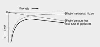
Diagram to illustrate the theory of the error curve for volumetric meters
If it is assumed that other external influences, e.g. gas inclusions in the liquid to be measured, are eliminated by appropriate measures, the following simplified statement can be made on the form of the error curve:
Gap losses always lead to negative errors (positive delivery error corresponds to a negative indication error).
The total gap loss is made up of two components:
The total curve can be formed from these two effects. It is characteristic for all positive displacement meters. To simplify things, the illustration "Error curves of volumetric meters" has been considerably enlarged.
Error curves of rotary-piston meters
The shape of the error curve is also affected by the viscosity of the metered liquid. The error in measurement increases with decreasing viscosity, especially at the beginning and towards the end of the flow rate range.
By appropriate regulation, i.e. changing a pair of gear-wheels between the meter mechanism and the register, the position of the error curve can be displaced parallel to the zero line and thus the meter can be optimally calibrated. The appropriate pair of replacement gears can be read off from a table or determined with the aid of a calculating disk.
The illustration "Error curves of volumetric meters" shows error curves without any regulation having been carried out.
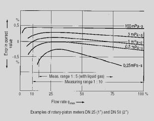
Error curves of volumetric meters dependent in shape and location on the flow rate and the viscosity of the liquid
Note: 1 mPa·s = 1 cp
The rotary-piston meters are approved in the European Community and in many other countries for the custody transfer.
The following error limits apply between 0.2 % and 0.5 % of the correct value (depending on the liquid, the measuring range and the relevant calibration specifications).
The stated error limits in % of the correct value apply to the whole flow rate and for any delivery quantity greater than the smallest permissible quantity.
This is an important difference compared to other measuring instruments whose errors are related to the full-scale value and thus only reach the stated accuracy at one point – full-scale deflection. The minimum flow rate should not fall below 10 % of the maximum flow rate in order to remain within the stated accuracy limit. This explains why the usual flow rate range for volumetric meters is 1:10.
Note:
The measuring system of the rotary-piston meter must always be filled with the liquid to be measured in order to achieve a high measuring accuracy.
The service life of a volumetric meter, i.e. the operating time until an overhaul or recalibration becomes necessary, is determined by the mechanical abrasion of the moving parts of the mechanisms which occurs because of forces from the metered liquid.
As well as the nature of the materials used (running characteristics), the service life is dependent on the lubricating properties of the metered liquid, the service is dependent on the lubricating properties of the metered liquid, the daily operating time and the cube of the flow rate (speed of rotation). The last factor is one of the reasons why only half of the maximum flow rate specified for the batch operation is permissible for continuous operation.
Since the above factors can hardly be determined exactly with industrial use of the meter, unequivocal statements on the service life (long-term accuracy) are not possible.
Recalibration is required every two years by law (in Germany) for meters used for custody transfer. On the basis of this regulation, it is recommended that meters which are not used for custody transfer be checked and recalibrated if necessary, at intervals of two to three years. This recommendation is also based on average, "normal" operating conditions. A period of 3 years is too short, for example, for a meter used for the batch dispensing of lubricating oil, it will still work within the stated error limits even after five years or more.
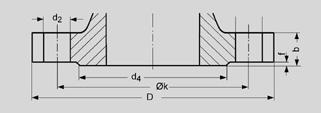
Flange dimensions
Dimensions of flanges drilled according to DIN
Dimensions of flanges with plain sealing face | Additional dimensions for flanges with raised face | |||||||||
|---|---|---|---|---|---|---|---|---|---|---|
Order No. | Material | Rated size DN | Pressure rating in PN | Ø D | Ø k | Number of holes | Ø d2 | b | Ø d4 | f |
mm | mm | mm | mm | mm | mm | mm | mm | |||
7MR1020 | E/S | 15 | 25 | 95 | 65 | 4 | 14 | 16 | 45 | 2 |
7MR1110/111• | E/S | 25 | 10 | 115 | 85 | 4 | 14 | 16 | 68 | 2 |
7MR1120 | E | 25 | 18 | |||||||
7MR1130 | E | 40 | ||||||||
7MR1140 | E | 63 | 140 | 100 | 4 | 18 | 24 | 68 | 2 | |
7MR1410/141• | E | 50 | 6 | 165 | 125 | 4 | 18 | 17 | 102 | 3 |
7MR1410/141• | S | 16 | ||||||||
7MR1420 | E | 25 | 20 | |||||||
7MR1430 | E | 40 | ||||||||
7MR1440 | E | 63 | 180 | 135 | 4 | 22 | 26 | – | – | |
7MR1610/161• | E | 80 | 4 | 190 | 150 | 4 | 18 | 18 | 128 | 3 |
7MR1610/161• | S | 6 | ||||||||
7MR1620 | E | 25 | 200 | 160 | 8 | 18 | 22 | 138 | 3 | |
7MR1630 | E | 40 | ||||||||
Dimensions of flanges drilled according to ASME
Dimensions of flanges with plain sealing face | Additional dimensions for flanges with raised face | |||||||||
|---|---|---|---|---|---|---|---|---|---|---|
Order No. | Material | Nom. diam. | Pressure rating in MWP | Ø D | Ø k | Number of holes | Ø d2 | b | Ø d4 | f |
inch | inch | inch | inch | inch | inch | inch | inch | |||
7MR1020 | E/S | 1/2 | 300 … 600 | 33/4 | 25/8 | 4 | 5/8 | 16 | 13/8 | 1/16 |
7MR1030 | E | |||||||||
7MR1110/111• | E/S | 1 | 150 | 41/4 | 31/8 | 4 | 5/8 | 16 | 2 | 1/16 |
7MR1120 | E | 300 … 600 | 47/8 | 31/2 | 4 | 3/4 | 18 | 2 | 1/16 | |
7MR1130 | E | |||||||||
7MR1140 | E | 900 … 1500 | 57/8 | 4 | 4 | 1 | 24 | 2 | 1/4 | |
7MR1410/141• | E/S | 2 | 150 | 6 | 43/4 | 4 | 3/4 | 17 | 35/8 | 1/16 |
7MR1420 | E/C | 300 … 600 | 61/2 | 5 | 8 | 3/4 | 20 | 35/8 | 1/16 | |
7MR1430 | E | |||||||||
7MR1440 | E | 900 … 1500 | 81/2 | 61/2 | 8 | 1 | 26 | 35/8 | 1/4 | |
7MR1610/161• | E/S | 3 | 150 | 71/2 | 6 | 4 | 3/4 | 18 | 5 | 1/16 |
7MR1620 | E | 300 … 600 | 81/4 | 65/8 | 8 | 7/8 | 22 | 5 | 1/16 | |
7MR1630 | E | |||||||||
Rotary-piston meter DN 15 (½“) without accessories
Rotary-piston meter DN 15 (½“) with single-pointer dial type 01, without heating device, dimensions in mm (inch)
Rotary-piston meter DN 15 (½“) with single-pointer dial type 01, with heating device, dimensions in mm (inch)
Rotary-piston meter with single-pointer dial type 01, (PN 25 (MWP 363 psi)) | ||
|---|---|---|
Dimensions | Heating device | |
With | Without | |
PN 25 (MWP 363 psi) | PN 25 (MWP 363 psi) | |
mm (inch) | mm (inch) | |
a1 | 224 (8.82) | 247 (9.72) |
a2 | 177 (6.97) | 200 (7.87) |
a3 | 140 (5.51) | 163 (6.42) |
c1 | 50 (1.97) | 66 (2.60) |
c2 | 83,5 (3.29) | 106 (4.17) |
g | - | 100 (3.94) |
h | - | G¾ |
hA | 37 (1.46) | 37 (1.46) |
l | - | 22 (0.87) |
See beginning of section for flange dimensions | ||
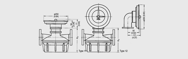
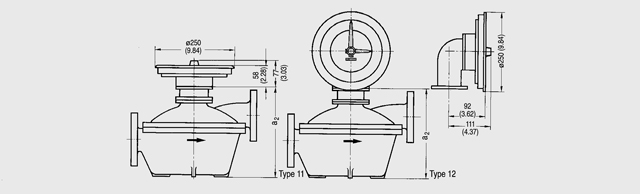
Rotary-piston meter DN 15 (½“) with double-pointer dial type 01, dimensions in mm (inch)
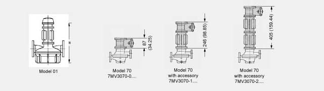
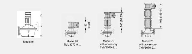
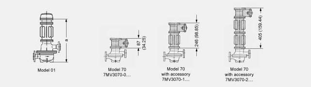
Rotary-piston meter with accessories
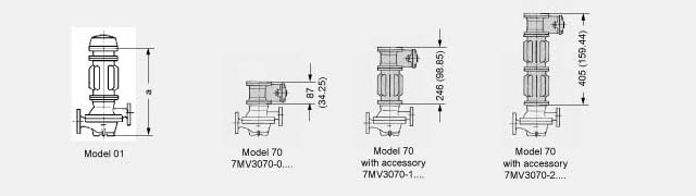
Rotary-piston meter DN 15 (½“) with accessories
Rotary-piston meter DN 15 (½“) with accessories, dimensions in mm (inch) | |
Design | 01 |
Dimension a for rotary-piston meter with 1 heat insulation attachment, dimensions in mm (inch) | |
Without heating device | |
| 336 (13:23) |
With heating device | |
| 359 (14.13) |
| 361 (14.21) |
Dimension a for rotary-piston meter with 2 heat insulation attachments, dimensions in mm (inch) | |
Without heating device | |
| 495 (19.49) |
With heating device | |
| 518 (20.39) |
| 520 (20.47) |
Rotary-piston meter DN 25 (1") without accessories
For pressure level PN 10 and PN 16 (MWP 145 psi and 232 psi)

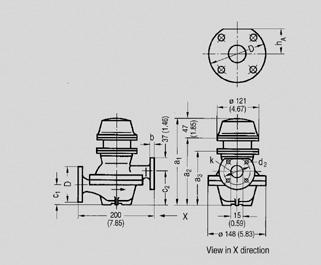
Rotary-piston meter DN 25 (1“) for PN 10 and PN 16 (MWP 145 psi and 232 psi) with single-pointer dial or with quantity preset register, dimensions in mm (inch)
Rotary-piston meter DN 25 (1“) for PN 10 and PN 16 (MWP 145 psi and 232 psi) with double-pointer dial, dimensions in mm (inch)
Rotary-piston meter DN 25 (1“) for PN 10 and PN 16 (MWP 145 psi and 232 psi) without accessories, dimensions in mm (inch) | |||||||||
|---|---|---|---|---|---|---|---|---|---|
With single-pointer dial type 01 or with double-pointer dial | |||||||||
a1 | a2 | a3 | c | d1 | e | g | h | hA | L |
237 (9.33) | 190 (7.48) | 153 (6.02) | 90 (3.54) | 14 (0.55) | 115 (4.53) | 155 (6.10) | 140 (5.51) | 48 (1.89) | 210 (8.27) |
With quantity preset register type 54 | |||||||||
a2 | a3 | a5 | c | g | h | hA | L | z | |
190 (7.48) | 153 (6.02) | 440 (17.32) | 90 (3.54) | 155 (6.10) | 140 (5.51) | 48 (1.89) | 210 (8.27) | 54 (2.10) for electric switch | |
See beginning of section for flange dimensions | |||||||||
For pressure level PN 25, PN 40 and PN 63 (MWP 363 psi, 580 psi and 914 psi)

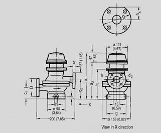
Rotary-piston meter DN 25 (1“) for PN 25, PN 40 and PN 63 (MWP 363 psi, 580 psi and 914 psi) with single-pointer dial or with quantity preset register, dimensions in mm (inch)
Rotary-piston meter DN 25 (1“) for PN 25, PN 40 and PN 63 (MWP 363 psi, 580 psi and 914 psi) with double-pointer dial, dimensions in mm (inch)
Rotary-piston meter DN 25 (1“) for PN 25, PN 40 and PN 63 (MWP 363 psi, 580 psi and 914 psi) without accessories, dimensions in mm (inch) | ||||||||
|---|---|---|---|---|---|---|---|---|
With single-pointer dial type 01 or with double-pointer dial | ||||||||
a1 | a2 | a3 | c1 | c2 | g | L | ||
| 292 (11.50) | 245 (9.65) | 208 (8.19) | 80 (3.15) | 144 (5.67) | 205 (8.07) | 270 (10.63) | |
| 308 (12.13) | 261 (10.28) | 224 (8.82) | 82 (3.23) | 157 (6.18) | 230 (9.06) | 300 (11.81) | |
With quantity preset register type 54 | ||||||||
a2 | a3 | a5 | c1 | c2 | g | L | z | |
| 245 (9.65) | 208 (8.19) | 495 (19.48) | 80 (3.15) | 144 (5.67) | 205 (8.07) | 270 (10.63) | 54 (2.10) for electric switch |
| 261 (10.28) | 224 (8.82) | 511 (20.12) | 82 (3.23) | 157 (6.18) | 230 (9.06) | 300 (11.81) | 54 (2.10) for electric switch |
See beginning of section for flange dimensions | ||||||||
Rotary-piston meter DN 25 (1“) with accessories
For pressure level PN 10 and PN 16 (MWP 145 psi and 232 psi)
Rotary-piston meter DN 25 (1“) for PN 10 and PN 16 (MWP 145 psi and 232 psi) with accessories, dimensions in mm (inch)
Rotary-piston meter DN 25 (1“) for PN 10 and PN 16 (MWP 145 psi and 232 psi) with accessories, dimensions in mm (inch) | |
Design | 01 |
Dimension a for rotary-piston meter with 1 heat insulation attachment | |
349 (13.74) | |
Dimension a for rotary-piston meter with 2 heat insulation attachments | |
508 (20.00) | |
For pressure level PN 25, 40 and 63 (MWP 363 psi, 580 psi and 914 psi)
Rotary-piston meter DN 25 (1“) for PN 25, PN 40 and PN 63 (MWP 363 psi, 580 psi and 914 psi) with accessories, dimensions in mm (inch)
Rotary-piston meter DN 25 (1“) for PN 25, PN 40 and PN 63 (MWP 363 psi, 580 psi and 914 psi) with accessories, dimensions in mm (inch) | |
Design | 01 |
Dimension a for rotary-piston meter with 1 heat insulation attachment | |
| 404 (15.91) |
| 420 (16.54) |
Dimension a for rotary-piston meter with 2 heat insulation attachments | |
| 563 (22.17) |
| 579 (22.80) |
Acid-resistant rotary-piston meter DN 25 (1“) without accessories
Acid-resistant rotary-piston meter DN 25 (1") for PN 10 (MWP 145 psi) with register or with quantity preset register; dimensions in mm (inch), see beginning of section for flange dimensions
Acid-resistant rotary-piston meter DN 25 (1") for PN 10 (MWP 145 psi) with double-pointer dial; dimensions in mm (inch), see beginning of section for flange dimensions
Acid-resistant rotary-piston meter DN 25 (1“) with accessories
Acid-resistant rotary-piston meter DN 25 (1") for PN 10 (MWP 145 psi) with accessories; dimensions in mm (inch)
Acid-resistant rotary-piston meter DN 25 (1") for PN 10 (MWP 145 psi) with accessories; dimensions in mm (inch) | |
Design | 01 |
Dimension a for rotary-piston meter with 1 heat insulation attachment | |
442 (17.40) | |
Dimension a for rotary-piston meter with 2 heat insulation attachments | |
601 (23.66) | |
Rotary-piston meter DN 50 (2") without accessories
For pressure level PN 6 and PN 16 (MWP 87 psi and 232 psi)
Rotary-piston meter DN 50 (2“) for PN 6 and PN 16 (MWP 87 psi and 232 psi) with single-pointer dial or with quantity preset register, dimensions in mm (inch)
Rotary-piston meter DN 50 (2“) for PN 6 and PN 16 (MWP 87 psi and 232 psi) with double-pointer dial, dimensions in mm (inch)
Rotary-piston meter DN 50 (2“) for PN 6 and PN 16 (MWP 87 psi and 232 psi) without accessories, dimensions in mm (inch) | |||||||||
|---|---|---|---|---|---|---|---|---|---|
With single-pointer dial type 01 or with double-pointer dial | |||||||||
a1 | a2 | a3 | c | d1 | e | g | h | hA | L |
289 (11.38) | 242 (9.53) | 205 (8.07) | 147 (5.79) | 18 (0.71) | 165 (6.50) | 275 (10.83) | 250 (9.84) | 75 (2.95) | 325 (12.80) |
With quantity preset register type 54 | |||||||||
a2 | a3 | a5 | c | g | h | hA | L | z | |
242 (9.53) | 205 (8.07) | 492 (19.37) | 147 (5.79) | 275 (10.83) | 250 (9.84) | 75 (2.95) | 325 (12.80) | 54 (2.10) for electric switch | |
See beginning of section for flange dimensions | |||||||||
For pressure level PN 25, PN 40 and PN 63 (MWP 363 psi, 580 psi and 914 psi)
Rotary-piston meter DN 50 (2“) for PN 25, PN 40 and PN 63 (MWP 363 psi, 580 psi and 914 psi) with single-pointer dial or with quantity preset register, dimensions in mm (inch)
Rotary-piston meter DN 50 (2“) for PN 25, PN 40 and PN 63 (MWP 363 psi, 580 psi and 914 psi) with double-pointer dial, dimensions in mm (inch)
Rotary-piston meter DN 50 (2“) for PN 25, PN 40 and PN 63 (MWP 363 psi, 580 psi and 914 psi) without accessories, dimensions in mm (inch) | ||||||||
|---|---|---|---|---|---|---|---|---|
With single-pointer dial type 01 or with double-pointer dial | ||||||||
a1 | a2 | a3 | c1 | c2 | g | L | ||
| 347 (13.66) | 300 (11.81) | 263 (10.35) | 120 (4.7) | 205 (8.1) | 330 (12.99) | 400 (15.75) | |
| 369 (14.53) | 322 (12.68) | 285 (11.22) | 120 (4.7) | 230 (9.1) | 385 (15.16) | 470 (18.50) | |
With quantity preset register type 54 | ||||||||
a2 | a3 | a5 | c1 | c2 | g | L | z | |
| 300 (11.8) | 263 (10.4) | 550 (21.7) | 120 (4.7) | 205 (8.1) | 330 (12.99) | 400 (15.8) | 54 (2.10) for electric switch |
| 332 (12.7) | 285 (11.2) | 572 (22.5) | 120 (4.7) | 230 (9.1) | 385 (15.2) | 400 (15.8) | 54 (2.10) for electric switch |
See beginning of section for flange dimensions | ||||||||
Rotary-piston meter DN 50 (2“) with accessories
For pressure level PN 6 and PN 16 (MWP 87 psi and 232 psi)
Rotary-piston meter DN 50 (2“) for PN 6 and PN 16 (MWP 87 psi and 232 psi) with accessories, dimensions in mm (inch)
Rotary-piston meter DN 50 (2“) for PN 6 and PN 16 (MWP 87 psi and 232 psi), dimensions in mm (inch) | |
Design | 01 |
Dimension a for rotary-piston meter with 1 heat insulation attachment | |
401 (15.79) | |
Dimension a for rotary-piston meter with 2 heat insulation attachments | |
560 (22.05) | |
For pressure level PN 25, 40 and 63 (MWP 363 psi, 580 psi and 914 psi)
Rotary-piston meter DN 50 (2“) for PN 25, PN 40 and PN 63 (MWP 363 psi, 580 psi and 914 psi) with accessories, dimensions in mm (inch)
Rotary-piston meter DN 50 (2“) for PN 25, PN 40 and PN 63 (MWP 363 psi, 580 psi and 914 psi) with accessories, dimensions in mm (inch) | |
Design | 01 |
Dimension a for rotary-piston meter with 1 heat insulation attachment | |
| 459 (18.07) |
| 481 (18.94) |
Dimension a for rotary-piston meter with 2 heat insulation attachments | |
| 618 (24.33) |
| 640 (25.20) |
Rotary-piston meter DN 80 (3") without accessories
For pressure level PN 25 and PN 40 (MWP 363 psi and 580 psi)
Rotary-piston meter DN 80 (3“) for PN 25 and PN 40 (MWP 363 psi and 580 psi) with single-pointer dial or with quantity preset register, dimensions in mm (inch)
Rotary-piston meter DN 80 (3“) for PN 25 and PN 40 (MWP 363 psi and 580 psi) with double-pointer dial, dimensions in mm (inch)
Rotary-piston meter DN 80 (3“) for PN 25 and PN 40 (MWP 363 psi and 580 psi) without accessories, dimensions in mm (inch) | ||||||||
|---|---|---|---|---|---|---|---|---|
With single-pointer dial type 01 or with double-pointer dial | ||||||||
a1 | a2 | a3 | c1 | c2 | g | L | ||
| 415 (16.34) | 368 (14.49) | 331 (13.03) | 155 (6.10) | 271 (10.67) | 450 (17.72) | 540 (21.26) | |
With quantity preset register type 54 | ||||||||
a2 | a3 | a5 | c1 | c2 | g | L | z | |
| 368 (14.48) | 331 (13.03) | 618 (24.33) | 155 (6.10) | 271 (10.67) | 450 (17.72) | 540 (21.26) | 54 (2.10) for electric switch |
See beginning of section for flange dimensions | ||||||||
For pressure level PN 25, 40 and 63 (MWP 363 psi, 580 psi and 914 psi)
Rotary-piston meter DN 80 (3“) for PN 25, PN 40 and PN 63 (MWP 363 psi, 580 psi and 914 psi) with accessories, dimensions in mm (inch)
Rotary-piston meter DN 80 (3“) for PN 25 and PN 40 (MWP 363 psi and 580 psi) with accessories, dimensions in mm (inch) | |
Design | 01 |
Dimension a for rotary-piston meter with 1 heat insulation attachment | |
| 527 (20.75) |
Dimension a for rotary-piston meter with 2 heat insulation attachments | |
| 686 (27.01) |
| Код | Заказной номер | Описание | Вес (кг) | Заказать |
|---|---|---|---|---|
| 118939 | 7MR1020-.EE..-.... | кольцевой механический счетчик dn 15 pn 25 материал корпуса серый чугун материал измерительной камеры серый чугун с подогревом материал измерительного кольца: серый чугун | 9 | Заказать |
| 118940 | 7MR1020-.EK..-.... | кольцевой механический счетчик dn 15 pn 25 материал корпуса серый чугун материал измерительной камеры серый чугун с подогревом материал измерительного кольца:углерод | 9 | Заказать |
| 118941 | 7MR1020-.SE..-.... | кольцевой механический счетчик dn 15 pn 25 материал корпуса crnimo-сталь материал измерительной камеры: crnimo сталь без подогрева материал измерительного кольца: серый чугун | 9 | Заказать |
| 72396 | 7MR1020-.SG..-.... | кольцевой механический счетчик dn 15 pn 25 материал корпуса crnimo-сталь материал измерительной камеры: crnimo сталь без подогрева материал измерительного кольца: твердая резина | 9 | Заказать |
| 72397 | 7MR1020-.SH..-.... | кольцевой механический счетчик dn 15 pn 25 материал корпуса crnimo сталь материал измерительной камеры: crnimo-сталь без подогрева материал измерительного кольца: pctfe | 9 | Заказать |
| 118942 | 7MR1020-.SK..-.... | кольцевой механический счетчик dn 15 pn 25 материал корпуса crnimo сталь материал измерительной камеры: crnimo сталь без подогрева материал измерительного кольца:углерод | 9 | Заказать |
| 118943 | 7MR111.-.D...-.... | дозатор dn 25 pn 10 материал корпуса: серый чугун материл измерительной камеры: crnimo сталь | 38 | Заказать |
| 72398 | 7MR111.-.E...-.... | дозатор dn 25 pn 10 материал корпуса: серый чугун материл измерительной камеры: серый чугун | 38 | Заказать |
| 72399 | 7MR111.-.S...-.... | дозатор dn 25 pn 10 материал корпуса: crnimo сталь материл измерительной камеры: crnimo сталь | 38 | Заказать |
| 72400 | 7MR1110-.E...-.... | кольцевой механический счетчик dn 25 pn 10, материал корпуса серый чугун, материл измерительной камеры: серый чугун | 10.5 | Заказать |
| 72401 | 7MR1110-.S...-.... | кольцевой механический счетчик dn 25 pn 10, материал корпуса crnimo сталь, материл измерительной камеры: crnimo сталь | 10.5 | Заказать |
| 118944 | 7MR1111-.PH..-.... | rotary-piston meter dn 25 acid-resistant rated pressure pn 10 measuring chamber parts peek with pctfe rotary piston meter pressure equipment direktive f. liquids 1 art. 3.3 sep | 28 | Заказать |
| 72402 | 7MR1111-.PK..-.... | rotary-piston meter dn 25 acid-resistant rated pressure pn 10 measuring chamber parts peek with pctfe rotary piston meter pressure equipment direktive f. liquids 1 art. 3.3 sep | 28 | Заказать |
| 118945 | 7MR1120-.E...-.... | кольцевой механический счетчик dn 25 pn 25 материал корпуса: серый чугун материл измерительной камеры: серый чугун | 20 | Заказать |
| 72403 | 7MR1130-.E...-.... | кольцевой механический счетчик dn 25 pn 40 материал корпуса стальное литье, материл измерительной камеры серый чугун, . уплотнение корпуса из fpm | 24 | Заказать |
| 118946 | 7MR1140-.E...-.... | кольцевой механический счетчик dn 25 pn 63 материал корпуса: стальное литье, материл измерительной камеры: серый чугун | 30 | Заказать |
| 72404 | 7MR141.-.D...-.... | дозатор dn 50 pn 6 материал корпуса: серый чугун материл измерительной камеры: crnimo сталь | 58.5 | Заказать |
| 72405 | 7MR141.-.E...-.... | дозатор dn 50 pn 6 материал корпуса: серый чугун материл измерительной камеры: серый чугун | 58.5 | Заказать |
| 118947 | 7MR141.-.S...-.... | дозатор dn 50 pn 10 материал корпуса: crnimo сталь материл измерительной камеры: crnimo сталь | 58.5 | Заказать |
| 118948 | 7MR1410-.E...-.... | кольцевой механический счетчик dn 50 pn 6, материал корпуса: серый чугун, материл измерительной камеры:серый чугун | 31 | Заказать |
| 118949 | 7MR1410-.S...-.... | кольцевой механический счетчик pn 10, материал корпуса crnimo сталь, материл измерительной камеры: crnimo сталь | 31 | Заказать |
| 118950 | 7MR1420-.C...-.... | кольцевой механический счетчик dn 50 pn 25, материал корпуса серый чугун, материл измерительной камеры: бронза | 45 | Заказать |
| 118951 | 7MR1420-.E...-.... | кольцевой механический счетчик dn 50 pn 25, материал корпуса серый чугун, материл измерительной камеры: серый чугун | 45 | Заказать |
| 118952 | 7MR1430-.E...-.... | кольцевой механический счетчик dn 50 pn 40, материал корпуса стальное литье,, материл измерительной камеры: серый чугун уплотнение корпуса из fpm | 60 | Заказать |
| 72406 | 7MR1440-.E...-.... | кольцевой механический счетчик dn 50 pn 63, материал корпуса стальное литье,, материл измерительной камеры: серый чугун | 94 | Заказать |
| 72407 | 7MR1620-.E...-.... | кольцевой механический счетчик dn 80 pn 25, материал корпуса серый чугун, материл измерительной камеры: серый чугун | 108 | Заказать |
| 72408 | 7MR1630-.E...-.... | кольцевой механический счетчик dn 80 pn 40, материал корпуса стальное литье,, материл измерительной камеры: серый чугун уплотнение корпуса из fpm | 150 | Заказать |
