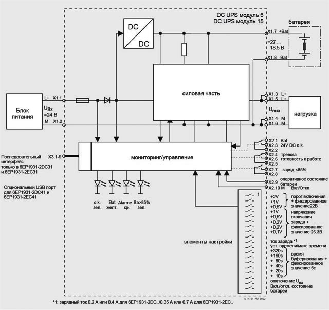
Компактные модули бесперебойного питания DC UPS с выходным током 6 A, 15 A или 40 A обладают обширными функциями защиты и контроля рабочего состояния для обеспечения надежной работы, такими как, контроль за готовностью к работе, за состоянием батареи, сроком службы и статусом заряда. Установить связь с этими модулями можно с помощью различных интерфейсов, например USB.
Набор доступных батарейных модулей состоит из версии с емкостью 2.5 Ач, предназначенной для широкого диапазона температур окружающей среды (от -40 °C до +60 °C) и версий с емкостью от 1.2 Ач до 12 Ач для стандартного диапазона температур. (от 5 °C до +40 °C).
Примечание: В связи с тем, что батарейные модули принадлежат к категории "опасные товары", стоимость их доставки может быть увеличена.
Ток нагрузки | Модуль батареи 1.2 Ач | Модуль батареи 3.2 Ач | Модуль батареи 7 Ач | Модуль батареи 12 Ач (6EP1935-6MF01) | Модуль батареи 2.5 Ач |
|---|---|---|---|---|---|
1 A | 30 мин | 2.5 ч | 6 ч | 11 ч | 2 ч |
2 A | 11 мин | 45 мин | 2.5 ч | 5 ч | 45 мин |
3 A | 4 мин | 25 мин | 1.5 ч | 3 ч | 30 мин |
4 A | 2 мин | 20 мин | 45 мин | 2 ч | 20 мин |
6 A | 1 мин | 10 мин | 30 мин | 1 ч | 13 мин |
8 A | - | 4 мин | 20 мин | 40 мин | 9 мин |
10 A | - | 1.5 мин | 15 мин | 30 мин | 7 мин |
12 A | - | 1 мин | 10 мин | 25 мин | 5.5 мин |
14 A | - | 50 c | 8 мин | 20 мин | 4.5 мин |
16 A | - | 40 c | 6 мин | 15 мин | 4 мин |
20 A | - | - | 2 мин | 11 мин | - |
Важная информация для подбора необходимой емкости батареи:
Рекомендуется:
Температура батареи | Падение до уровня 50% от начальной емкости | Рекомендации: замена всех батарей (при 100% остаточной емкости) | Альтернативные рекомендации |
|---|---|---|---|
+20 °C | 4 года | 2 года |
|
+30 °C | 2 года | 1 год |
|
+40 °C | 1 год | 0.5 года | Установка двойной емкости и замена каждый год. |
В обычных условиях (монтаж в самое прохладное место шкафа при +30 °C), батареи, установленные без запаса емкости, должны быть заменены в соответствии со сроком, указанным в таблице, по истечении 1 года работы.
The following timing diagrams show examples of the characteristic of the input and output voltage at the terminals of the DC-UPS module as well as the signal characteristic of the alarm signals (relays) and of the remote signal (port).
Power restoration only once buffer time tp has expired (t3 follows t4):
Upon failure of the input voltage on the DC UPS module (time t1), the battery "Bat" immediately takes over the DC supply, and the output voltage Vout is then retained absolutely without interruption.
The isolated changeover contact "OK/Bat" switches over to its off position "Bat".
At the same point in time t1, the buffer time tp set on the DIP switches is started automatically.
The fact that the DIP switch is set to "Interruption output Vout" in this example has no effect because the input voltage returns at time t3 only once the set buffer time (time t4) has expired.
Power restoration before buffer time tp has expired (t3 before t4):
Upon failure of the input voltage on the DC UPS module (time t1), the battery "Bat" immediately takes over the DC supply, and the output voltage Vout is then retained absolutely without interruption.
The isolated changeover contact "OK/Bat" switches over to its off position "Bat".
At the same point in time t1, the buffer time tp set on the DIP switches is started automatically.
With the DIP switch set to "Interruption output Vout", the output voltage Vout is automatically interrupted for 5 s once the set buffer time tp (time t4) has expired.
The battery has already been disconnected because the input voltage has returned at the time t3.
If the DIP switch is not set to "Interruption output Vout", there is no interruption in this example because the input voltage has already returned at time t3 prior to expiry of the set buffer time (time t4).

Figure 1 "Long power failure"
Figure 2 "Short power failure"
DC UPS without serial or USB port (6EP1 931-2DC21/-2EC21/-2FC21)
DIP switch settings on device: buffer time tp (from 5 s to 635 s with bottom row nos. 2 to 7) /
t = according to setting (with bottom row no. 1 to left) / xxxx = with setting for interruption Vout (with bottom row no. 8 to left)
Legend:
Vin: Input voltage at terminals X1.1 – X1.2
Vout: Output voltage at terminals X1.3 – X1.4 and X1.5 - X1.6
ok: Signal for input voltage Vin OK or above the set battery connection threshold
Bat: signal for battery operation (batteries connected to output, batteries power the load)
Remote: Signal for remote timer start with signal level = 0 at pin 7 of 9-pin serial interface (pin 7 is usually the positive power supply for the interface)
t1: Input voltage Vin missing or falls below set connection threshold
t2: Buffer time set on DIP switches is started by remote timer start (signal level = 0)
t3: Input voltage Vin rises above set connection threshold
t4: End of set buffer time (output is switched off and/or battery is disconnected)
t5: Output is connected again 5 s after shutdown
tp: Buffer time set on the DIP switches (bottom row nos. 2 to 7)
Power restoration only once buffer time tp has expired (t3 follows t4):
Upon failure of the input voltage on the DC UPS module (time t1), the battery "Bat" immediately takes over the DC supply, and the output voltage Vout is then retained absolutely without interruption.
The isolated changeover contact "OK/Bat" switches over to its off position "Bat".
The buffer time tp set on the DIP switches is started at the user-selectable time t2 by means of the signal "Remote timer start" (signal level = 0 at pin 7 of the 9-pin serial interface following previous signal chart according to operating instructions).
The fact that the DIP switch is set to "Interruption output Vout" in this example has no effect because the input voltage returns at time t3 only once the set buffer time (time t4) has expired.
Note: Without a remote signal level = 0 with a setting t = max. duration, there is no interruption to the output voltage in this case because the set buffer time is not started (or interruption only if the exhaustive discharge protection disconnects the accumulator and the input voltage has not returned by then).
Power restoration before buffer time tp has expired (t3 before t4):
Upon failure of the input voltage on the DC UPS module (time t1), the battery "Bat" immediately takes over the DC supply, and the output voltage Vout is then retained absolutely without interruption.
The isolated changeover contact "OK/Bat" switches over to its off position "Bat".
The buffer time tp set on the DIP switches is started at the user-selectable time t2 by means of the signal "Remote timer start" (signal level = 0 at pin 7 of the 9-pin serial interface following previous signal chart according to operating instructions).
With the DIP switch set to "Interruption output Vout", the output voltage Vout is automatically interrupted for 5 s once the set buffer time tp (time t4) has expired.
The battery has already been disconnected because the input voltage has returned at the time t3.
The interruption to the output voltage Vout for 5 s permits an automatic restart for many industrial PCs, even if the line voltage (or the input voltage Vin on the DC UPS module) returns during shutdown of the PC, as in this example.
Note: Without a remote signal level = 0 with a setting t = max. duration, there is no interruption in the output voltage here because the set buffer time is not started.
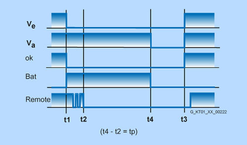
Figure 3 "Long power failure"
Figure 4 "Short power failure"
DC UPS with serial or USB port (6EP1 931-2DC31/-2DC42/-2EC31/-2EC42/-2FC42)
DIP switch settings on device: buffer time tp (from 5 s to 635 s with bottom row nos. 2 to 7) /
t = max. time (with bottom row no. 1 to right) / interruption of Vout (with bottom row no. 8 to left)
Legend:
Vin: Input voltage at terminals X1.1 – X1.2
Vout: Output voltage at terminals X1.3 – X1.4 and X1.5 - X1.6
ok: Signal for input voltage Vin OK or above the set battery connection threshold
Bat: signal for battery operation (batteries to output, batteries supply the load)
Remote: Signal for remote timer start with signal level = 0 at pin 7 of 9-pin serial interface (pin 7 is usually the positive power supply for the interface)
t1: input voltage Vin missing or falls below set connection threshold
t2: Buffer time set on DIP switches is started by remote timer start (signal level = 0)
t3: input voltage Vin rises above set connection threshold
t4: end of set buffer time (output is switched off and/or battery is disconnected)
t5: Output is connected again 5 s after shutdown
tp: buffer time set on the DIP switches (bottom row nos. 2 to 7)