
SITRANS R200 is a display recorder that displays measured data on the LCD in real time and stores data in CompactFlash Card.
The type of input such as thermocouple, RTD, DC voltage (current), etc. can be arbitrarily set to 6 channels at the maximum.
The data stored in CompactFlash Card can be regenerated on the screen, and the use of supplied support software allows the data to be regenerated on a PC.
The data recorded in ASCII format can be directly read in a spreadsheet such as Excel, which facilitates the processing on a PC. The data recorded in binary format get analyzing by evaluation software.
Input system | |
Number of input points | 3 or 6 points |
Input circuit | Input mutual isolation |
| about 1 mA |
Measuring cycles | |
| 100 ms cycles |
| 1 s … 12 h |
Input types | Thermocouple, RTD, DC voltage, and DC current (Shunt resistors are fitted in input terminals). Note: Provide a shunt resistor separately. |
Measuring range | Note: B, R, S, K, E, J, T, N: JIS C 1602, DIN IEC 584-1 N : NICOSIL - NISIL (IEC 584) W: 5 % Re ... 26 % RE – W (Hoskins Mfg. Co. USA) L: Fe-Cu – Ni (DIN 43710) U: Cu-Cu – Ni (DIN 43710) PN: Platinum JPt100: JIS C 1604-1989 (old JIS Pt 100) Pt100, Pt50: JIS 1604, DIN IEC 751 Ni100: DIN 43760, 1979 |
Thermocouple | |
| 400 ... 1 760 °C (752 ... 3200 °F) |
| 0 ... 1 760 °C (32 ... 3200 °F) |
| 0 ... 1 760 °C (32 ... 3200 °F) |
| -200 ... 1 370 °C (-328 ... 2 498 °F) |
| -200 ... 800 °C (-328 ... 1 472 °F) |
| -200 ... 1 100 °C (-328 ... 2 012 °F) |
| -200 ... 400 °C (-328 ... 752 °F) |
| 0 ... 1 300 °C (32 ... 2 372 °F) |
| 0 ... 1 760 °C (32 ... 3 200 °F) |
| -200 ... 900 °C (-328 ... 1 652 °F) |
| -200 ... 400 °C (-328 ... 752 °F) |
| 0 ... 1 300 °C (32 ... 2 372 °F) |
RTD | |
| -200 ... 600 °C (-328 ... 1 112 °F) |
| -200 ... 600 °C (-328 ... 1 112 °F) |
| -60 ... 180 °C (-76 ... 356 °F) |
| -200 ... 600 °C (-328 ... 1 112 °F) |
| -50 ... 200 °C (-58 ... 392 °F) |
DC voltage | |
| 0.00 ... 50.00 mV |
| 0.0 ... 500.0 mV |
| 1.000 ... 5.000 V |
| 0.000 ... 5.000 V |
Selection of input types | By key operation on the front panel. Note that the same input type (thermocouple, RTD, voltage) should be selected for channel 4 and 5. |
Burn-out function | Equipped in thermocouple and RTD inputs as standard, and overswings the recording to 100 % side. |
| approx. 0.5 μA |
Input filter function | Settable for each channel (primary delay filter) Time constants are settable in the range from 0 … 900 s. |
Scaling function | DC voltage (current) input |
| -32767 ... 32767 |
| Settable at any point |
| Settable up to 7 digits and 125+12 types |
Subtraction function | Subtraction between each channel is allowed. |
Square rooter function | Square rooter can be performed against the input value per each channel. |
Indication system | |
Display | 5.7” STN color LCD (320 × 240 dots) with backlight Note: The LCD may have some pixels that do not stay on or off. Due to the characteristics of liquid crystal, the brightness may not be uniform, which is not a failure. |
Color of display | 14 colors |
Applicable language | English, German, French (switchable) |
Life of backlight | 50 000 h (20 °C/68 °F) |
Trend display | |
| Vertical and horizontal |
| 6 channels or 4 channels or 3 channels for the screen (Input: 6 points at the maximum). |
| Select from 1 s … 12 h No numerical value display. Scale display can be selected. |
Bar graph display | |
| Vertical |
| 6 channels or 4 channels or 3 channels for the screen (Input: 6 points at the maximum). |
| 1 s |
Digital display | |
| 6 channels or 4 channels for the screen (Input: 6 points at the maximum). |
| 1 s |
Event summary display | Alarm summary and message summary can be displayed. |
Ethernet log display | E-mail sending, FTP server log in/off and Modbus TCP/IP communication start/stop can be displayed. |
Parameter display/set | Already-set Data Display and Set Change Display screen |
Tag indication | |
| Up to 8 characters at 6 channels on one screen or up to 16 (= 8 x 2) characters at 4 channels on one screen. |
| Alphanumerical characters |
| It depends on the screen. See table “Tag indication”. |
Historical trend display | The past data can be displayed from the Compact Flash or internal memory. The past data fi le can be read and displayed with scroll display function or jump the cursor to the position which you entered date and time. Scale display/no-display can be selected. |
Number of screen groups | 1 group (up to 6 channels per 1 group can be registered) |
Keyboard | |
No. of Keys | 8 |
Function | Use to select various screens and set various parameters. |
Recording function | |
External memory media | Compact Flash card (format as FAT16 or FAT, or recorder can’t read and write) |
Recording capacity | 1 Gbyte maximum (compact flash) Limiting the recording file to 64 Mbyte is recommended (for 112 hours if display refresh cycle is 1 second (see Table “Recording capacity”). If impossible, up to 256 Mbyte is tolerated. A file recorded beyond could not be opened. Note: Only the Sandisk‘s compact flash is warranted. And please change the compact flash every six month to prevent the data losing. |
Recording method | Turning on the “REC” key allows measured data to be written at fi xed cycles. Recorded as a new file whenever the recording starts. |
Data save cycles | Linked to the display refreshment cycles on the “Trend display” screen. However, they are automatically set to about 1 minute if the refreshment cycles are set to less than 1 minute. |
Trend data | Average, instance or min. and max. measured values out of measured data that are sampled at the measuring cycles are saved. |
Event data | Saves alarm data, message data and power ON data when the power turns off and on during recording. |
Storage capacity | Approximately 2 years when the display refresh cycle is 30 s (in case of 6-channel recording in ASCII data format, and 256 Mbyte compact flash used). Refer to „Recording capacity“ |
Memory usage | Indicates the memory which has already used on the screen. When all the memory is used up, you can stop recording or delete the oldest recording file to save the newest data. |
Recommended card | SanDisk http://www.sandisk.com Type: SDCFB-256 (256 Mbyte). |
Recommended PC card adaptor | SanDisk Corp. SDAD-38 |
Data format | Either of ASCII or binary format can be selected. (Switching cannot be made while the recording is in progress. In the case of ASCII format, the data can be directly read on Excel, etc.) Note: The data recorded in binary format cannot be read directly. Approximately 118 bytes per sample (for 6-channel input in ASCII format) or approximately 28 bytes (for 6-channel input in binary format). |
Alarm function | |
No. of settings | Up to 4 alarms for each channel are settable |
Type of alarm | High/Low limits |
Indication | Status (alarm types) is displayed on digital display unit when an alarm occurs. History display on alarm summary (Alarm start/cancel time and alarm types) |
Hysteresis | Set within the recording range of 0 … 100 % (it is effective only in case of high/low limit alarm) |
Relay output | Number of points: 10 |
Alarm latch function | Keeps alarm indication and alarm output turning on after alarm reset. ON/OFF operation is performed according to key setting. |
Power supply | |
Rated power voltage | 100 … 240 V AC |
Range of operating voltage | 90 … 264 V AC |
Supply frequency | 50/60 Hz (both employable) |
Power consumption | 100 V AC: About 32 VA 240 V AC: About 42 VA |
Design | |
Mounting method | Panel-mounted (vertical panel) |
Thickness of panel in mm (inch) | 2 … 26 (0.079 … 1.024) |
Materials | PC-ABS for case and bezel |
Color | Grey |
External dimensions | Panel-mounted: |
Weight | About 1.5 kg (no option) |
External terminal | Screw terminals (M3) |
RJ45 | Ethernet terminal (option) |
Operating condition | |
Power voltage | 90 … 264 V AC |
Supply frequency | 50/60 Hz ± 2 % (both employable) |
Ambient temperature | Panel-mounted: 0 … 50 °C (32 … 122 °F) (without Ethernet option) 0 … 40 °C (32 … 104 °F) (with Ethernet option) Note: In case of 30 °C (86 °F) or more of ambient temperature, this display might be fogged little bit. This is not out of order. |
Ambient humidity | 20 … 80 % RH |
Vibration | 10 … 60 Hz, 0.2 m/s² or less |
Shock | None |
Magnetic field | 400 A/m or less |
Signal source resistance | |
| 1 kΩ or less |
| 10 Ω/wire or less (resistance of each wire of 3-wire system should be balanced) |
| 0.1 % or less of input resistance |
Mounting position | Forward tilt 0°, backward tilt within 30°, horizontal 0° |
Warm-up time | 1 h or more after power ON |
Environmental protection | IEC IP50 (Front) / IP20 (Terminal) |
Safety and EMC standard | |
Safety standard | Based on IEC 61010-1 |
EMC standard | Based on EN 61326 |
Transportation/storage conditions | |
Temperature | -10 … +60 °C (14 … 140 °F) |
Humidity | 5 ... 90 % RH, no condensation |
Vibration | 10 ... 60 Hz, 2.45 m/s² or lower |
Shock | 294 m/s² or lower (packed state) |
Reference standard | |
Accuracy/resolution | Measuring conditions (23 ± 2 °C, 65 ± 10 % RH, power voltage, frequency fl uctuation within ± 1 %, no external noise, warm-up time of 1 hour or more, vertical mounting, standard values of signal source resistance and wiring resistance within 1 %) Note 1: Digital indication accuracy is a percentage (%) of the value in the measuring range. |
Thermocouple | |
| Digital indication accuracy:
|
| |
| |
| |
| |
| |
| |
| |
| |
| |
| |
| |
RTD | |
| Digital indication accuracy: ± (0.15 % + 1 digit) Digital indication resolution: 0.1 °C (32.18 °F) |
| |
| |
| Digital indication accuracy: ± (0.5 % + 1 digit) Digital indication resolution: 0.1 °C (32.18 °F) |
| |
DC voltage | |
| Digital indication accuracy: ± (0.15 % + 1 digit) Digital indication resolution: 10 μV |
| Digital indication accuracy: ± (0.15 % + 1 digit) Digital indication resolution: 100 μV |
| Digital indication accuracy: ± (0.15 % + 1 digit) Digital indication resolution: 1 mV |
| |
Error of reference contact compensation | When measured at 0 °C (32 °F) or more:
|
Max. input voltage | Thermocouple, RTD: |
Input resistance | Thermocouple, DC voltage: about 1 MΩ |
Others | |
Clock | With calendar function (Christian era) Accuracy: ± 50 ppm or less (monthly error: about 2 minutes) |
Memory backup | Parameters are saved to the internal nonvolatile flash memory. The clock and totalized data are backed up with built-in lithium battery. |
Isolation resistance | 100 MΩ or more (when measured between each terminal and ground) |
Test voltage | |
| 2 000 V AC, 1 min |
| 500 V AC, 1 min |
| 2 000 V AC, 1 min |
| 750 V AC, 1 min |
| 500 V AC, 1 min |
Effect on operation | |
Effect of power supply fluctuation conditions | |
| Reading change: ± (0.2 % + 1 digit) or less |
| Reading change: ± (0.2 % + 1 digit) or less |
Effect of input signal resistance | |
| 0.5 μV/Ω + 1 digit or less |
| Fluctuation for resistance value equivalent to 0.1 % of the input resistance: ± (0.2 % + 1 digit) or lower. |
| Reading change: ± (0.2 % + 1 digit) or lower |
Effect of ambient temperature | Reading change: ± (0.3 % + 1 digit)/10 °C (50 °F) or lower |
Effect of mounting position | For the backward 30° slant Reading change: ± (0.2 % + 1 digit) or lower |
Effect of vibration | When sine wave of 10 … 60 Hz with the acceleration of 0.2 m/s² is applied in each direction for 2 hours. Reading change: ± (0.2 % + 1 digit) or lower |
Normal mode noise | ≥ 20 dB at 50, 60 Hz ± 0.1 Hz |
Common mode noise | ≥ 120 dB at 50, 60 Hz ± 0.1 Hz |
Additional function (option) | |
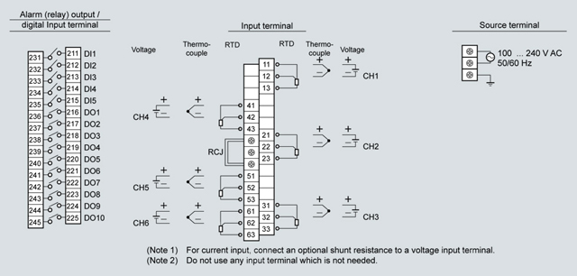
Alarm relay output/DI | A card with 10-point relay output and 5-point DI input can be mounted. |
External terminal | M3 screw terminal |
Alarm relay output | Contact output (SPST:10 points), |
| Contact rating: |
| Contact rating: |
DI input | No-voltage contact input (5 points) The following control is allowed by contact input.
|
| 200 ms or longer |
| 200 ms or longer |
Ethernet (option) | The following can be performed through the Ethernet function. |
HTTP server (Internet Explorer 6 is available) | Note: Neither Netscape nor Mozilla Firefox are available. |
| Digitally displays the measurement of each channel of the recorder and alarm occurrence status. |
| Displays event summary including alarm ON/OFF and issuance of messages. |
| Displays memory use conditions and information on the main unit such as the battery end warning. |
| Digitally displays the integrated value of each channel of the recorder. |
FTP server (Internet Explorer 6, is available) | Note: Neither Netscape nor Mozilla Firefox are available. |
| Record files stored in compact flash (CF) can be downloaded from the browser. |
| Record files stored in CF can be deleted from the browser. |
| Authenticates access authority to FTP server. |
SMTP (e-mail client) | Transmits e-mails to specified address under the following conditions.
|
Modbus TC/IP | |
| Settings can be read through Modbus TCP/IP communication. |
| Settings can be written through Modbus TCP/IP communication. |
Support software | The following software is provided as standard.
|
Parameter loader software | |
Major function | Performs various parameter setting/change of the main unit |
O/S | Windows 2000/XP |
Required memory | 64 Mbyte or larger |
Disk drive | Windows 2000/XP-capable CD-ROM drive |
Hard disk capacity | Free capacity of 30 Mbyte or larger required |
Printer | Windows 2000/XP-capable printer and printer driver Note: PC loader communication cable is separately required. |
Data viewer software | |
Major function | Regenerates the past trend record on the PC from the data in the Compact Flash. Provided with historical trend display and event display functions. |
O/S | Windows 2000/XP |
Required memory | 64 Mbyte or larger |
Disk drive | Windows 2000/XP-capable CD-ROM drive |
Hard disk capacity | Free capacity of 30 Mbyte or larger required |
Printer | Windows 2000/XP-capable printer and printer driver |
Screen | Number of channel on one screen | Items | |||
|---|---|---|---|---|---|
Tag 1 | Tag 2 | Unit | Channel number | ||
Trend | 4 or less | + | + | + | + |
5 or more | x | x | x | ||
Bar graph | 4 or less | + | + | + | + |
5 or more | x | x | x | ||
Digital | All items are displayed | ||||
x: Only 1 item can be displayed
+: Only 2 items can be displayed
Function | Description |
Record range voluntary setting | Recording range can be set by channel. |
Input type setting | Input can be set by channel (key operation on the front face). Set the same input type for channel 4 and 5. See “Selecting input type”. |
Skip function | Skips arbitrary channel display/recording. |
Trend display | |
| Time is displayed at the top of the trend display screen. |
| On occurrence of an alarm and the restoration, alarm is displayed in the alarm display field. |
Tag name display | By channel, maximum of 8 characters. |
Screen name display | Displays the screen name (maximum of 16 characters). |
Unit creation | Industrial units can be arbitrarily created, Maximum of 7 digits, 12 types. |
Scaling function | Arbitrary scaling is allowed in the case of DC voltage input. Decimal point position can also be arbitrarily set in the range from -32767 … 32767. |
PV shift | Shift the zero point and slant of the reading. |
Input filter | Prevents sudden fluctuation of input for each channel (primary delay filter). Time constant: 0 … 900 s. |
Burnout function | Displays the break of thermocouple/RTD input by scaling out to 100 % side. |
Historical trend display | Regenerates and displays the data stored in the compact flash by scrolling the screen or jump to time when you entered. |
If the number of input points is 6, there are no events such as messages, and the data format is ASCII, the recording can be made for the period of time listed in the tables shown below.
Compact Flash size | 64 Mbyte | ||||
|---|---|---|---|---|---|
Display refreshment cycle | 1 s | 10 s | 30 s | 1 min | 10 min |
Recordable capacity (about) | 112 hours | 66 days | 199 days | 398 days | 10.9 years |
Compact Flash size | 256 Mbyte | ||||
Display refreshment cycle | 1 s | 10 s | 30 s | 1 min | |
Recordable capacity (about) | 26 days | 265 days | 2 years | 4.3 years | |
When Compact Flash is not used
The input types of channel 4 and 5 is the same.
The following input types are available. The following input types are available.
Input category | Details |
Thermocouple, 50 mV | K, E, J, T, R, S, B, N, W, L, U, and PN thermocouples, 50 mV |
RTD | Pt100, JPt100, Ni100, Pt50, Cu50 |
500 mV | 500 mV |
5 V | 1 ... 5 V, 0 ... 5 V |
Input type | Input category | Description | |
|---|---|---|---|
Channel 1 | K thermocouple | Thermocouple, 50 mV | |
Channel 2 | 1 ... 5 V | 5 V | |
Channel 3 | 500 mV | 500 mV | |
Channel 4 | K thermocouple | Thermocouple, 50 mV | The input type of the thermocouple and 50 mV is the same. |
Channel 5 | 50 mV | ||
Channel 6 | JPt100 | RTD |
Measured data is periodically stored in CompactFlash Card. Storage capacity of up to 256 Mbyte allows display files for approximately 2 years to be recorded continuously at the display refresh cycle of 30 seconds (in the case of ASCII data format, 6 channels).
Data stored in CompactFlash Card can be displayed in succession by scrolling the screen.
Depending on the object of measurement, the most suitable display format can be selected from a variety of formats including bar graph display, trend display, digital display, etc.
Parameter loader software that enables easy display and change of set data and data viewer software that regenerates the data stored in CompactFlash Card are supplied as standard.
160 x 144 x 185 (Width x Height x Depth in mm, Panel mounting), 1.5 kg.
FTP, Web server, e-mail and Modbus-TCP are available.
If the non-operation exceeds the setting value of parameter, “LCD lights-out time”, recorder turns off the backlight. Setting range of this parameter is 0 to 60 minutes.
In the case of 3 or 6-point input
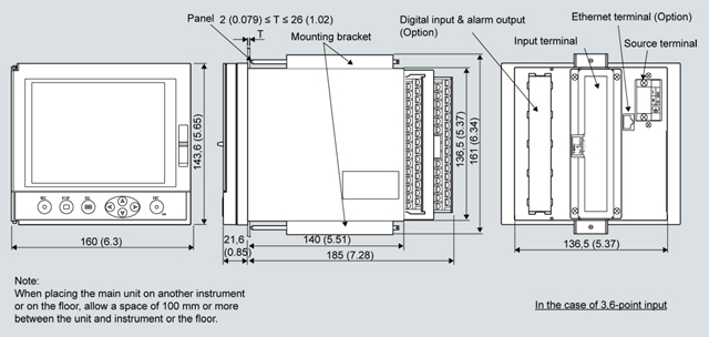
All dimensions in mm (inch)
All dimensions in mm (inch)
In the case of 3 or 6-point input
Additional information is available in the Internet under:
| Код | Заказной номер | Описание | Вес (кг) | Заказать |
|---|---|---|---|---|
| 72471 | 7ND5120-.....-.... | sitrans r200 displayrecorder, 5 inch screen | 2 | Заказать |
| 119015 | 7ND5801-7AA | 10 ohm external shunt resistor (required for dc current input) | 0.01 | Заказать |
| 72472 | 7ND5801-7AB | pc card adaptor for compact flash card | 0.3 | Заказать |
| 119016 | 7ND5801-7AC | termination resistor for communication | 0.01 | Заказать |
