
Set FLK
The Set FLK (liquid/air cooling) is a standardized set for gas sampling.
Continuous analysis of flue gas in the rotary kilns of cement factories is essential for the quality of the generated clinker, the efficient use of fuel, and protection of the environment from toxic emissions:
In a rotary cement kiln, gas samples are usually taken from the intake area by means of a system such as the FLK gas sampling probe, and the concentrations of oxygen (O2), carbon monoxide (CO) and nitrogen oxide (NO) measured continuously.
During cement production, the largest share of production costs results from the amount of fuel used. On the one hand, complete combustion is important for reducing toxic materials in the exhaust gas, on the other hand an excess of oxygen is a waste of resources. Already an oxygen excess of 1 % means an increased energy consumption of 15 kcal per kg of generated clinker.
Measurement of the concentrations of O2 and CO permits the furnace operator to optimize the combustion in the rotary kiln with respect to the quality of the generated clinker, reduction in toxic emissions, and reduced use of fuels.
The NO concentration in the rotary kiln largely depends on the flame temperature. A temperature held as constant as possible in the clinkering zone is of great significance for a high quality of the generated clinker. Variations in the clinkering zone temperature result in significant changes in the NO concentration.
The NO analysis is therefore an appropriate means for achieving stable and uniform operation of the kiln. Use of an NO2 converter for measuring nitrogen oxides (NO and NO2) is not recommended since with this analysis the variation is more important than the absolute value of the nitrogen oxide concentration.
Because of the increasing share of alternative fuels, some of which have very high sulfur concentrations, analysis of SO2 in the rotary kiln is becoming increasingly important. High concentrations of SO2 in the gas circuits result in increased corrosion and frequently to undesirable caking of material in the rotary kiln and in the cyclones of the heat exchanger. In addition, a fast rise in the SO2 concentration is an early warning of a combustion fault.
The difficult environmental conditions in rotary kilns place high demands on the sampling systems. Problematical are the high gas temperature up to 1400 °C, the high dust concentration of up to 2000 g/m3 and the high concentrations of alkali, sulfate and chloride in the gas circuits. In addition, the gas sampling probe is subject to high mechanical stress resulting from falling material or the inflowing raw meal.
In particular, high concentrations of sulfur and alkali very frequently result in blockages in the gas paths, necessitating over-proportionally high maintenance of the gas sampling equipment.
The FLK gas sampling probe uses a heat transfer liquid with a boiling point of above 300 °C as the coolant. The temperature of the sampled flue gas is up to 200 °C, and is above its acid dew point. This reliably prevents condensation of the flue gas, which, together with the existing dust, can rapidly result in blockages.
General information | |
Power supply | 400 V 3AC +10%/-15%, 50 Hz 400 V 3AC +10%/-15%, 60 Hz Connected load: approx. 5.5 kVA If the delta voltage deviates, a single-phase supply must be provided in addition: 120 V 3AC +10%/-15%, 50 Hz 120 V 3AC +10%/-15%, 60 Hz 230 V 3AC +10%/-15%, 50 Hz 230 V 3AC +10%/-15%, 60 Hz Connected load: approx. 1.5 kVA Other voltages up to 500 V possible on request |
Auxiliary media | |
| 6 000 ... 8 000 hPa, purified compressed air, free of oil, water and dust |
| Approx. 4 ... 6 m3/h, depends on purging frequency and duration |
Sample gas connection | 8 mm pipe union, connection for heated or unheated sample gas line; required pump capacity at 700 hPa absolute approx. 2 to 5 l/min |
Liquid-cooled sampling probe | |
Type | F6534-B12 |
Material | Stainless steel, mat. No. 1.4571 |
Length | 1 000/1 500/2 000/2 500/3 000/3 500 mm (corresponds to immersion depth) |
Sampling point | Dependent on installation:
|
Process temperature | Up to 1 400 °C |
Coolant | Synthetic heat transfer liquid |
Coolant flow rate | Max. 3 200 l/h |
Weight | Approx. 150 kg |
Electrically heated dust filter | |
Power supply | See General information |
Filter | Sintered metal filter SIKA-R30 (3 μm for 98 %) Filters with smaller pore sizes available on request |
Operating temperature | Approx. 200 °C, isolated contact for low temperature |
Backflushing, two-stage (filter element and filter surface) | 6 000 ... 8 000 hPa, purified compressed air, free of oil, water and dust |
Compressed air connection | Filter enclosure ¾" Filter pipe ½" |
Sample gas connection | |
| Male thread M24x1.5 |
| Pipe union DN 8 |
Weight | Approx. 20 kg |
Compressed air valve manifold | |
Power supply | See General information |
Compressed air connection | 6 000 ... 8 000 hPa, purified compressed air, free of oil, water and dust |
Ambient temperature | Max. 70 °C |
Maximum operating pressure | 16 000 hPa |
Pressure switch | 800 ... 200 hPa absolute, adjustable for detection of low pressure |
Dimensions (WxHxD) in mm | 630 x 380 x 210 |
Weight | Approx. 40 kg |
Retraction unit with electrical and pneumatic drive | |
Power supply | See General information |
Drive |
|
Travel time | Approx. 90 s |
Dimensions | Type 1: 3 780 mm for probe length 1 000 ... 1 500 mm Type 2: 5 300 mm for probe length 2 000 ... 3 500 mm |
Weight | Approx. 420 kg |
Heat exchange unit | |
Power supply | See General information |
Heat output | Max. 65 kW |
Coolant | Synthetic heat transfer liquid |
Fill quantity | Approx. 25 l |
Flow | Max. 3 200 l/h, adjustable |
Operating temperature | |
| 200 °C |
| 170 °C |
Dimensions (WxHxD) in mm | 1 200 x 1 850 x 1 600 |
Weight | Approx. 400 kg |
Control and monitoring unit | |
Power supply | See General information |
Control voltage | 24 V DC |
Signals | Floating contacts to the host process control system |
Dimensions (WxHxD) in mm | 760 x 760 x 210 |
Weight | Approx. 60 kg |
The FLK gas sampling system consists of the following components:
The probe is available with an immersion depth of between 1 500 and 3 500 mm. It is manufactured from stainless steel mat. no. 1.4571 and its oval shape gives it a high vertical flexion strength. The sampling point is at the tip of the probe on the side pointing away from the flow in order to suck in as little dust as possible from the gas.
The probe is suitable for process gas temperatures of up to 1 400 °C.
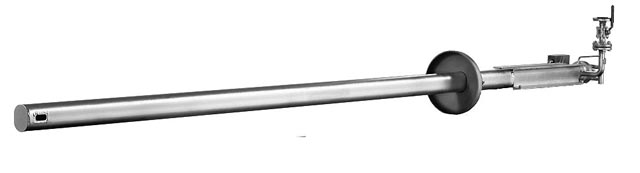
Liquid-cooled sampling probe
The dust filter is used to purify the gas/dust mixture extracted from the process area, and is suitable for dust loads of up to 2 000 g/m3.
Electrical heating up to a temperature of approx. 200 °C prevents crustation or caking of the filter pipe.
Cleaning is carried out automatically at regular intervals, using compressed air at a pressure of approx. 8 bar. To avoid blockage of the filter pores, the compressed air must be free of oil and water residues. Oil residue in particular can lead to caking in the filter pores, which then cannot be removed using compressed air cleaning.
Depending on the dust load, the dust filter can be fitted with filter pipes with different pore sizes.
Electrically heated dust filter
Together with the PLC, the valve manifold carries out the regular cleaning programs for purging the gas sampling system.
The purging frequency and duration can be adapted to the conditions of the respective plant using the operator panel of the control unit.
Purging can be initiated manually at any time using the integrated pushbutton. An integrated pressure switch detects imminent blockages in the gas paths as early as possible, and initiates immediate purging of the gas sampling system by sending a signal to the control unit.
A condensation trap is fitted on the valve manifold for preliminary separation of condensation and dust from the process gas.
The sample gas is cut off from the downstream gas preparation by means of a four-way solenoid valve with metal-free gas paths.
For purging purposes, compressed air that is free from dust, water and oil and has a pressure of approximately 8 000 hPa must be provided.
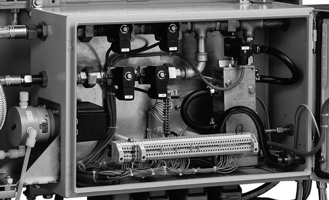
Compressed air valve manifold
In the event of an incident, the retraction unit automatically removes the probe from the rotary kiln in order to protect it against thermal overload. Depending on the probe length, approx. 90 seconds are required up to complete retraction. An electrical geared motor is used as the drive.
Faults that result in immediate retraction of the probe are:
Should the power supply fail, emergency retraction of the probe is carried out by a pneumatic motor provided the supply with compressed air is guaranteed. For maintenance purposes, the probe can be manually retracted at any time using a pushbutton.
The heavy-duty industrial design of the retraction unit guarantees reliable and practically maintenance-free operation.
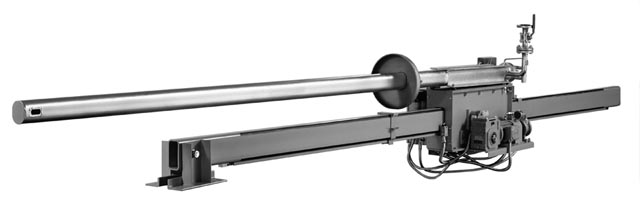
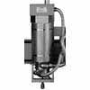
Retraction unit with electrical and pneumatic drive
The gas sampling probe is cooled by means of a depressurized air/liquid heat exchanger. Use of a synthetic heat transfer liquid with a boiling point above 300 °C permits temperatures of up to 200 °C in the cooling circuit, and therefore equivalent gas sampling temperatures.
To prevent condensation of the flue gas in the gas sampling equipment, gas sampling is only enabled if the temperature in the cooling circuit is at least 130 °C.
The temperature in the cooling circuit is kept as constant as possible by controlling the flow by means of a speed-controlled circulation pump. Depending on the temperature, the flow can be between 1 000 and 3 500 m3/h.
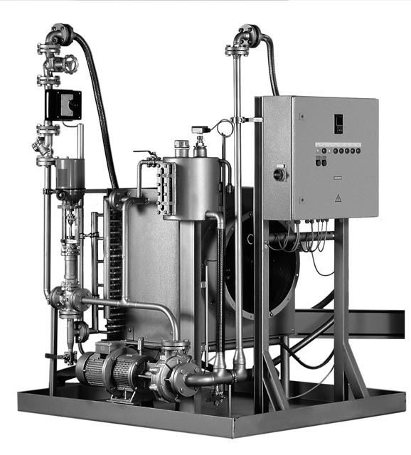
Heat exchange unit
The core of the FLK gas sampling equipment is the compact control and monitoring unit with Siemens SIMATIC S7-300 programmable logic controller. The equipment is optionally available with an Allen Bradley SLC500 controller.
In addition to the monitoring functions for safe operation of the probe, the control unit is also responsible for regular cleaning of the gas paths.
The operator can use an integrated operator panel to adjust all the parameters, such as the frequency and duration of probe purging, to suit the requirements of the respective plant. No programming knowledge is required to do this.
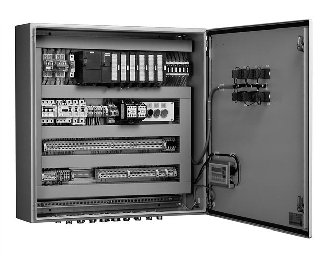
Control and monitoring unit
Installation of the FLK probe
A number of points must be observed to permit low-maintenance operation of the gas sampling equipment:
In case of doubt, please consult an expert.
Installation of the heat exchanger
The heat exchanger should be installed close to the probe, and at the same level if possible. The coolant lines should be kept as short as possible to avoid falsification of the coolant temperature in the probe. Excessive heat radiation on the coolant lines can lead to overheating of the probe in the extreme case since the coolant temperature is measured in the heat exchanger. If the heat exchanger has to be installed further away from the probe for space reasons, the coolant lines must be insulated against heat loss.
Strictly observe the information in the manual when connecting the coolant lines.
The heat exchanger has a thermal output of up to 65 kW. Sufficient ventilation for dissipation of the heat must be provided. During operation, the surfaces of the heat exchanger can reach a temperature of up to 250 °C. To protect against touching by mistake, customers must provide a protective grid around the heat exchanger.
Installation of the retraction unit
A space of approx. 6 000 mm is required behind the probe's mounting location for installation of the retraction unit. If the required space is not available, the retraction unit can be shortened depending on the probe length. For a probe with an immersion depth of 2 500 mm, the minimum length of the retraction unit is approx. 4 700 mm.
The dust filter and valve manifold supplied separately must be fitted to the side of the retraction unit during the mounting.
Installation of the control cabinet
The control cabinet should preferably be installed in a dust-proof room, usually the analyzer room.
Routing of sample gas line
Particularly with non-heated sample gas lines, a continuous downward gradient must be provided from the sampling point to the analyzer cabinet in order to avoid water pockets. Any resulting condensation must be able to flow off before the analyzer cabinet.
A heated sample gas line is absolutely essential when measuring SO2 or if there is a danger of freezing.
In order to achieve T90 times which are as low as possible, the nominal diameter of the sample gas line should be selected as small as possible.
Flow | for 1 m gas line upstream of gas analyzer | |
|---|---|---|
Nominal diameter 4 mm | Nominal diameter 6 mm | |
0.5 l/min | 1.6 s | 4.3 s |
1.0 l/min | 0.8 s | 2.1 s |
1.5 l/min | 0.6 s | 1.5 s |
2.0 l/min | 0.4 s | 1.1 s |
Delayed display depending on flow rate
Compressed air connection
A compressed air connection with a pressure of 6 000 to 8 000 hPa is required to purge the probe and for operation of the pneumatic motor. The compressed air must be free of oil, water and dust. Moisture in the compressed air results in premature blockage of the pores in the dust filter and increased maintenance effort.
Oil in the compressed air can result in caking of the filter pores which can no longer be removed, necessitating replacement of the sintered metal filter.
Electrical connections
The electrical connections must be made according to the directives of the local power supply company and the directives of the respective country.
A period of approx. 5 days should be calculated for mounting. Mounting is usually carried out by the customer.
Commissioning
Starting up of the complete equipment should always be carried out by trained Siemens personnel. Prior to startup, the installation must be checked for observation of the directives according to the manuals.
Starting up should be carried out with the kiln in operation in order to carry out the required settings and optimization.
A period of approx. 3 to 5 days should be calculated for starting up.
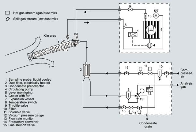
Mode of operation
The process gas to be analyzed is sampled by the gas sampling probe, purified in the electrically heated dust filter, and then applied to the gas analyzer. Because the opening is positioned at the side, only a part of the gas flow which has a particularly low dust concentration is sampled.
To reduce the load on the gas cooler in the analyzer cabinet, a condensation trap is present on the valve manifold. During purging of the sampling equipment, the resulting condensation is discharged from the tank.
During operation in an environment up to 1 400 °C, the probe is cooled by a heat exchanger operating at atmospheric pressure. An electronic control valve provides short heating-up times following initial insertion of the probe, and controls the temperature of the coolant in the cooling circuit.
Comprehensive monitoring mechanisms protect the probe from thermal overloading. In the event of a malfunction, the probe is automatically removed from the rotary kiln by the retraction unit.
The harsh environmental conditions at the intake of the rotary kiln result in extreme loads on the sampling probe. The process gas temperature can be up to 1 400 °C, and the dust load up to 2 000 g/m3. Caked-on materials falling down from the kiln lining present a danger for the probe through mechanical overloading.
Depending on the raw material and the fuels used, an increasing amount of sulfur, alkali and chlorides can be expected in the flue gas, which in turn may result in caking of material on the probe jacket and the production of corrosive acids.
To achieve as high an availability as possible with a minimum amount of maintenance effort, the mounting location for the probe must be determined exactly. If you are not sure about the most favorable installation location, obtain support from the supplier.
Many problems frequently encountered when using a gas sampling function in a rotary kiln can be largely avoided using the FLK probe. As a result of the high gas sampling temperature of up to 200 °C, problems associated with caking on the probe jacket and blocking of the gas paths by condensation are significantly reduced compared to water-cooled sampling systems which only achieve a gas sampling temperature of approx. 90 °C.
Cleaning of the gas sampling equipment is carried out at regular intervals using pulsed compressed air. Prior to starting the backflushing, the gas path to the gas analyzer is closed by means of a four-way ball valve. As a result of the self-cleaning effect during the rotation, the ball valve has significant advantages compared to a standard solenoid valve.
The cleaning cycle is executed in several steps:
A pressure switch in the compressed air valve manifold detects imminent blockages in the gas paths between the planned purging times, and initiates immediate purging by means of the control unit.
The quantity and hardness of the caking on the probe jacket can be extremely different with different types of rotary kiln. In addition to possible mechanical overloading of the probe, the temperature of the sampled flue gas drops as a result of the thermal insulation from the hot process gases. This results in condensation of the flue gas in the probe's sampling tube. If a temperature of 130 °C is fallen below, the sample gas pump in the analyzer cabinet is switched off as protection against the production of condensation. Caking must therefore be removed regularly.
In order to remove caking, the probe can be automatically retracted from the rotary kiln at regular intervals, initiated by the control unit of the sampling equipment and depending on the amount of caking. Caking is usually removed automatically from the probe jacket as a result of cooling down in the cold ambient air. When retracting and inserting the probe, cleaning of the probe jacket is supported by passing compressed air through nozzles in the kiln connection tube. In unfavorable cases, manual cleaning by the maintenance personnel may be necessary.
The numerous control and monitoring functions are made possible by the PLC.
Adaptation of the control parameters - such as purging frequency and duration - can be carried out at any time using the integrated operator panel.
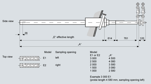
Liquid-cooled sampling probe, dimensions in mm
| Код | Заказной номер | Заказать |
|---|---|---|
| 70840 | 7MB1951-.....-.... | Заказать |
