
SITRANS SL is a diode laser gas analyzer with a measuring principle based on the specific light absorption of different gas components. SITRANS SL is suitable for fast, non-contact measurement of gas concentrations in process or flue gases. An analyzer consisting of transmitter and receiver units (sensors) is used for each measuring point. The hardware for further processing of the measured signal into a concentration value, as well as the monitoring, control and communication functions, are integrated in these two main modules. The sensors are designed for operation under harsh environmental conditions.
SITRANS SL
The following table lists the measuring conditions for standard applications. The listed values for the measuring range and detection limit are only approximate values. The exact values at the respective measuring point depend on the totality of all influencing variables and can be determined by Siemens for the specific case. Please note that the values for the detection limit and the maximum measuring range refer to an optical path of 1 m. Longer path lengths will improve the detection limit, but not linearly. due to limiting effects such as dust load. The maximum applicable measuring ranges can only be used if permitted by the process conditions such as dust load.
Standard application | Process gas temperature | Process gas pressure | Min. measuring range | Max. measuring range | Max. measuring range x path length | DL x path length | Repeatability3) | Purging gas medium | ||
|---|---|---|---|---|---|---|---|---|---|---|
Sample gas component | Gas code | Appl. code | ||||||||
O2 | A | B | 0 … 600 °C | 900 … 1 100 hPa | 0 … 1 vol% | 0 … 100 vol% | 75 vol%*m | 200 ppmv*m | 2 % | N2 |
O2 | A | C | 0 … 200 °C | 700 … 5 000 hPa | 0 … 1 vol% | 0 … 100 vol% | 75 vol%*m | 200 ppmv*m | 2 % | N2 |
CO | J | C | -20 … 700 °C | 700 ... 2 000 hPa, max. 300 °C 800 ... 1 200 hPa, above 300 °C | 0 … 100 ppmv | 0 … 6 000 ppmv | 2 000 ppmv*m | 0.6 ppmv*m | 2 % | Air, N2 |
Reference table: Standard applications. The specified pressures are absolute.
DL = detection limit
1) At 20 °C, 1 013 hPa, without dust
2) With 0.3 m effective optical path length
Average diameter of the dust particles: 15 µm
Specific weight of the dust particles: 650 kg/m3
The influence of dust load is extremely complex, and depends on the path length and particle size. The optical damping increases exponentially at longer path lengths. Smaller particles also have a very large influence on the optical damping. With high dust load, long path length and small particle size, the technical support at Siemens should be consulted.
3) Referred to measuring range.
With stable or externally measured and software-compensated process gas temperature and pressure conditions.
In addition to the standard applications, special applications are available upon request.
The in-situ SITRANS SL gas analyzer features high operational availability, unique analytical selectivity, and a wide range of possible applications. SITRANS SL permits measurement of a gas component directly in the process:
Special features of the SITRANS SL:
Moreover, the analyzer provides warning and error messages:
Analytical performance | |
Measuring range | Internally adjustable |
Detection limit at standardized conditions: | O2: 200 ppm CO: 0.6 ppm |
Linearity (under standard conditions) | Better than 1% |
Repeatability (under standard conditions) | O2: 1% of the measuring range CO: 0.5 % of the measuring range |
General information | |
Design | Transmitter and detector units, connected by a sensor cable |
Materials |
|
Installation | In-situ or bypass |
Concentration units | ppm, vol. %, mg/Nm3 |
Display | Digital concentration display (4 digits with floating decimal point) |
Laser protection class | Class 1, safe to the eye |
Explosion protection | Optionally, according to
|
Design, enclosure | |
Degree of protection | IP65 according to EN 60529 |
Dimensions | For each unit (transmitter, detector)
|
Purging tube | Length, outer diameter, inner diameter: |
Weights | |
| 6.0 kg |
| 5.2 kg |
| |
| 5.3 kg |
| Approx. 12 kg |
Connection dimension customer flange | DN 50/PN 25 or ANSI 4"/150 lbs |
Electrical characteristics | |
Power supply | 24 V DC nominal (18 ... 30.2 V DC) |
Power consumption, maximum | 10 VA |
EMC | In accordance with EN 61326-1 |
Electrical safety | In accordance with EN 61010-1 |
Fuse specifications | T1.6L250V |
Dynamic performance | |
Warm-up time at 20 °C ambient temperature | Approx. 15 min |
Response time (T90) | Approx. 2 s, depends on application |
Integration time | 0 ... 100 s, selectable |
Influencing variables | |
Variations in ambient temperature | < 0.5%/10 K of the measuring range |
Process gas temperature | With compensation: < 1 %/100 K of the measuring range |
Variations in ambient pressure | Negligible |
Process gas pressure | O2: With compensation: < 1%/4 000 hPa of the measuring range CO: Negligible |
Variations in supply voltage | Negligible |
Electrical inputs and outputs | |
Number of measurement channels | 1 |
Analog outputs | 2 outputs, 4 ... 20 mA, floating, ohmic resistance max. 660 Ω. External isolating power supplies may have to be provided by the customer. |
Analog inputs | 2 inputs, designed for 4 ... 20 mA, 120 Ω |
Binary outputs | 2 outputs, with switchover contacts, configurable, 24 V/0.5 A, floating, single pole double throw (SPDT) |
Binary input | 1 input, designed for 24 V, floating, configurable |
Service port | Ethernet 10BaseT (RJ-45) |
RS 485 PROFIBUS DPV0 version | Two-wire interface, up to 3 Mbit/s, -7 … 12 V |
RS 485 Modbus version | Two-wire interface, up to 115 200 bit/s, -7 … 12 V |
Cable to customer interface (not included in standard delivery, ATEX or optional) | |
Analog connection cable | 10 x 2, with shielding in twisted-pair configuration (depending on type and number of I/Os used) |
PROFIBUS DP connection cable | 1 x 2 + 4 (PROFIBUS DP hybrid cable) |
Modbus connection cable | 1 x 2 + 3, with shielding in twisted-pair configuration |
Cable length for ATEX configuration | 3 m |
Conductor cross-section | Min. 0.34 mm² |
Cable diameter | 8 ... 12 mm or 13 ... 18 mm |
Minimum bending radius ATEX-PROFIBUS | 110 mm |
Sensor cable (not included in standard delivery, ATEX or optional) | |
Sensor cable type | 4 x 2, with shielding, in twisted-pair configuration |
Conductor cross-section | Min. 0.34 mm² |
Cable sheath | PUR (polyurethane) |
Dimensions |
|
Minimum bending radius | ATEX: 85 mm |
Climatic conditions | |
Ambient temperature range |
|
Temperature range on the sensor side of the process interface (connection plate) | -20 ... +70 °C |
Atmospheric pressure | 800 ... 1100 hPa |
Humidity | < 100 % rel. humidity |
Measuring conditions | |
Measurement path | 0.3 ... 8 m (other lengths: please contact Siemens) |
Process gas pressure, temperature |
|
Dust load | The influence of a high dust load is complex, and depends on the optical path length and particle size distribution. |
Purging | |
Purging gas |
|
| O2 application: Purity better than 99.7 % in order to achieve full performance. For oxygen measurements, an O2 content < 0.01 vol. % in the purging gas is recommended. |
| < -10 °C, condensation on the optics must be avoided |
Sensor purging | |
| 500 hPa |
| 0 ... +55 °C |
| O2 application: When commissioning a sensor enclosure previously filled with air: 3 ... 5 l/min (for at least 15 min), subsequently: at least 0.25 l/min |
Purging on process side (optional) | |
| 2 000 ... 8 000 hPa |
| Dependent on process gas pressure, process gas velocity, dust load, moisture, etc. up to max. 50 l/min |
The SITRANS SL gas analyzer consists of a pair of cross-duct sensors, a transmitter unit and a detector unit, both with the same dimensions. The complete analyzer is integrated in these two enclosures. The transmitter unit contains the laser source whose light is transmitted to the receiver through the measurement path. The detector unit contains a photodetector including electronics as well as a reference cell. The detector unit is connected to the transmitter unit by means of a sensor cable. A further cable on the receiver is used to connect the power supply and the communication interfaces. The receiver enclosure contains a local user interface (LUI) with an LC display which can be read through a window in the cover. The LUI is operated by remote-control.
Special features of the transmitter and detector units:
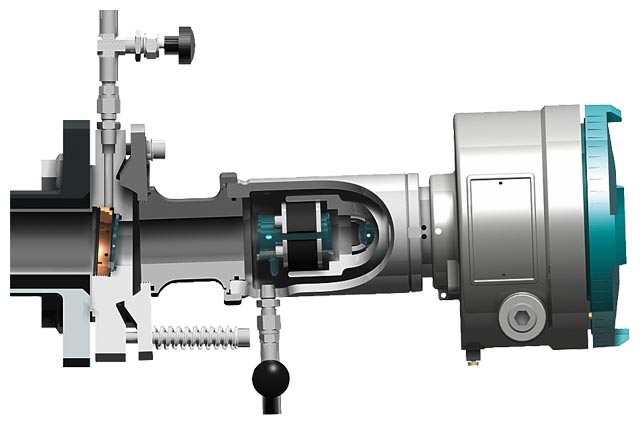
SITRANS SL, detector unit
Parts in contact with the process gas
Only the stainless steel and borosilicate window flange of the sensor is wetted by the process gas. This has optional connections for purging the process gas side with an appropriate gaseous medium.
Special features of the detector unit:
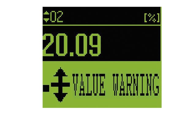
Local user interface (LUI) of SITRANS SL in the detector unit (display of measured value)

Remote control keypad for SITRANS SL
SITRANS SL is supplied as standard without connecting cables. These must be provided by the customer or are available as accessories. Exception: the ATEX version is supplied as standard with cabling.
The sensor cable connects together the transmitter and detector units of the analyzer.
The sensor connecting cable available as a cable set for the ATEX version as standard, and for non-Ex applications optionally, is offered in lengths of 5, 10 or 25 m. This (optional) cable set also enables permanent installation of an Ethernet cable used for service and maintenance purposes.
A rugged cable sleeve should be used as UV protection for installations in open cable ducts or channel systems.
The statutory directives must be observed in the event of installation in hazardous areas.
For the ATEX version of SITRANS SL, the sensor connecting cable must be connected between the two Ex-e terminal boxes secured on the transmitter and receiver units.
The PROFIBUS DP protocol provides DPV0, cyclic data. Measured values are provided with additional quality data.
Optional
Note:
In contrast to the other interfaces, the Ethernet plug-in connector on standard non-Ex devices is only accessible following removal of the detector unit cover. With the help of the sensor connection cable set (optional with non-Ex devices), an Ethernet cable can be permanently installed via the terminal box of the sensor connecting cable. The Ethernet connection via the sensor connecting cable can also only be used for temporary service and maintenance purposes.
NOTICE:
In an Ex environment, Ethernet connections may only be made or removed with the permission of the plant operator!
SITRANS SL is a gas analyzer employing single-line molecular absorption spectroscopy. A diode laser emits a beam of infrared light which passes through the process gas and is received by a detector unit. The wavelength of the laser diode output is tuned to a gas-specific absorption line. The laser continuously scans this single absorption line with a very high spectral resolution. The degree of absorption and the line shape are used for the evaluation. The measurement is free of cross-interferences, since the quasi-monochromatic laser light is absorbed very selectively by only one specific line in the scanned spectral range.
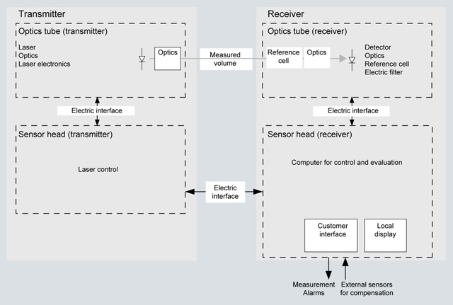
Basic design of the SITRANS SL
The field design of the SITRANS SL in-situ gas analyzer consists of a transmitter unit and a detector unit. The light which is not absorbed by the sample is detected in the receiver. The concentration of the gas component is determined from the absorption.
The SITRANS SL analyzer measures a single gas component by means of the absorption capacity of a single fully resolved molecular absorption line.
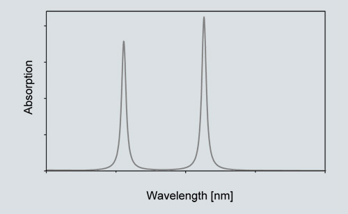
Absorption spectrum of measured signal and reference signal with SITRANS SL
SITRANS SL is designed for measuring oxygen (O2) and carbon monoxide (CO) at high sensitivity.
Typical application specifications:
Oxygen concentration | 0 ... 21 vol % |
Process pressure/temperature conditions (with O2 application) | 700 ... 5 000 hPa (absolute)/0 ... 200 °C 900 ... 1 100 hPa (absolute)/0 ... 600 °C |
Carbon monoxide concentration | Smallest measuring range: 0 … 100 ppm @ 1 m Largest measuring range: 0 … 6 000 ppm @ 30 cm |
Process gas pressure/temperature conditions with CO application | 700 … 2 000 hPa (absolute) / -20 … 300 °C 800 … 1 200 hPa (absolute) / -20 … 700 °C |
The measuring performance of the SITRANS SL depends, among others, on the actual, individual process conditions with regard to concentration ranges, pressure and temperature.
An internal reference cell is used to constantly check the stability of the spectrometer.
The self-calibration of the analyzer is therefore valid for at least one year without the necessity for external recalibration using calibration gases.
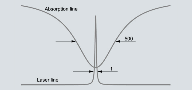
Typical spectral bandwidth of an absorption line compared to the bandwidth of the laser light.
Configuration
A feature of the in-situ analytical procedure is that the physical measurement takes place directly in the stream of process gas and directly in the actual process gas line. All process parameters such as gas matrix, pressure, temperature, moisture, dust load, flow velocity and mounting orientation can influence the measuring properties of the SITRANS SL and must therefore be investigated for each new application.
The standard applications listed in the ordering data for the SITRANS SL are distinguished in that the typical process conditions are adequately well-known and documented. If you cannot find your application among the standard applications, please contact Siemens. We will be pleased to check your possible individual application of the SITRANS SL. You can find an application questionnaire on the SITRANS SL product site on the Internet.
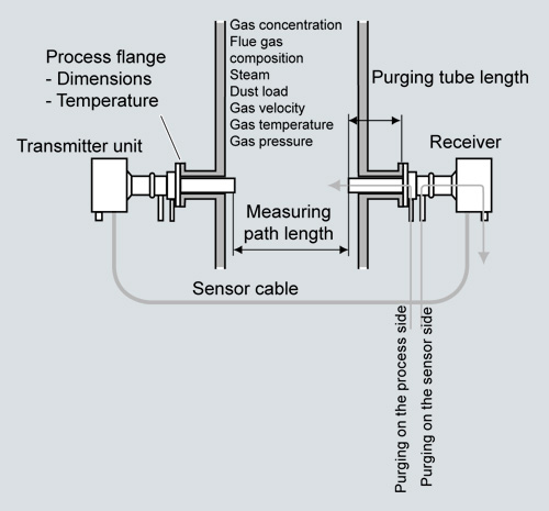
Typical cross-duct arrangement of the SITRANS SL
The SITRANS SL can be optionally purged on the process side using appropriate purging gases to prevent contamination of the sensor optics on the process side. Purging tubes on the sensor heads, which slightly extend into the process gas stream, define the effective measuring path length.
Dust load
As long as the laser beam is able to generate a suitable detector signal, the dust load in the process gas does not influence the analytical result. By applying a dynamic background correction, measurements can be carried out without any negative impact. Under optimal conditions, the SITRANS SL can cope with dust loads up to 20 g/Nm³ and up to a measured path length of 8 m. The influence of a high dust load is extremely complex, and depends on the optical path length and particle size. The optical damping increases exponentially at longer path lengths. Smaller particles also have a very large influence on the optical damping. With high dust load, long path length and small particle size, the technical support at Siemens should be consulted.
Temperature
The influence of temperature on the absorption line is compensated by a correction file. A temperature signal can be fed into the instrument from an external temperature sensor. The signal is then used for mathematical correction of the influence of the temperature on the observed line strength. If the process gas temperature remains constant, a static correction can be carried out as an alternative. Without temperature compensation, the relative error caused by changes in the gas temperature has an extensive effect on the measurement (e.g. up to 0.24 %/K with the O2 application). An external temperature signal is therefore recommended in most cases.
Pressure
The process gas pressure can affect the line shape of the molecular absorption line. For known pressure values, the SITRANS SL uses a special algorithm to adapt the line shape. Additionally, an external pressure signal can be fed to the instrument to provide complete mathematical compensation for the pressure influence including the density effect. Without compensation, the relative error caused by changes in the process gas pressure is approx. 0.1 %/hPa. An external pressure signal is therefore recommended in most cases.
Interferences
Since the SITRANS SL derives its signal from a single fully resolved molecular absorption line, interferences from other gases are quite unlikely. The SITRANS SL is therefore able to measure the desired gas components very selectively. In special cases, the composition of the process gas might have an influence on the shape of the absorption lines. This influence is compensated by analyzing the full shape of the detected signal curve applying specific algorithms.
Effective optical path length
As a result of Beer-Lambert’s law, the absorption of laser light depends on the optical path length within the sample gas. Therefore the precision of the effective optical path length measurement can have an effect on the precision of the total measurement.
Since the sensor optics on the process side usually has to be purged to keep it clean for a longer period, the extent of the mixed zone between the purging medium and the process gas as well as the latter's concentration distribution must be considered. In a typical in-situ installation with an optical path length of several meters, the influence of the purging gas on the effective path length can be ignored.
The path length and dust load are mutually influencing: the higher the dust load in the process, the shorter the max. possible path length.
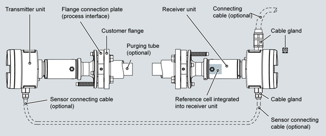
Design of the non-Ex version of the SITRANS SL system
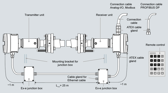
Design of the ATEX version of the SITRANS SL system
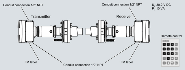
Design of the FM version of the SITRANS SL system
The transmitter and detector units are mounted on process flanges provided by the customer. Correct alignment of these flanges must be guaranteed, e.g. by using the optional sensor alignment kit.
Adjustment of the pair of sensors
The flange connection plates (process interface) of the SITRANS SL to the process flanges on the customer side must be correctly aligned so that the laser beam generated by the transmitter hits the photodetector in the detector unit This is guaranteed in that the transmitter and detector units have a curved surface integrated in the connection plates. The adjustment is carried out by shifting the flanges on these surfaces, through which the symmetry axis is aligned. The axis can be offset by ± 1 degree, which means that the process flanges must be welded onto the process wall with at least this accuracy - see following figure.
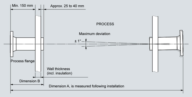
Installation/adjustment requirements for the pair of cross-duct sensors
Purging
The easiest way to avoid condensation and dust deposits on the sensor windows or excessively high thermal load of the windows and the sealing material as well as the sensor electronics is to purge them (with O2 application: nitrogen). Purging must be selected depending on the application. The transmitted-light sensors can therefore be configured for the respective situation. The application reference table provides recommendations for suitable purging for the standard applications.
If oxygen is to be measured with the SITRANS SL - which is also present in measurable quantities in the ambient air - oxygen-free purging gases must be used, such as nitrogen. It is equally necessary to purge the inside of the sensor heads, since the ambient air must also be displaced here out of the laser beam path. A differentiation is therefore made between purging on the process side and purging on the sensor side.
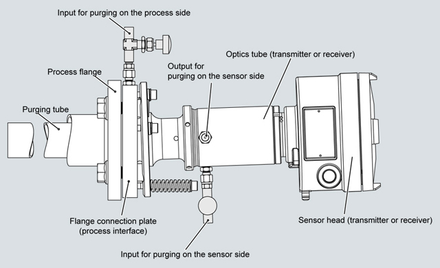
Arrangement for purging on the sensor side of the SITRANS SL
Purging on process side
For purging on the process side, the flow of purging gas can be adjusted between 0 and approx. 50 l/min at each sensor head using a needle valve (included in delivery).
Purging on sensor side
This can be combined with the purging on the process side, if required. Purging with nitrogen on the sensor side is almost always necessary for O2 applications to avoid an offset caused by the oxygen of the air present in the unit. The cells in the sensor head are then continuously purged with nitrogen. Particularly when (re)starting the SITRANS SL O2, a sufficiently high flow of purging gas of approx. 3 to 5 l/min must be provided for several minutes to ensure that all residues of oxygen are displaced. The flow of sensor purging gas can subsequently be set to a lower value using the needle valve (included in delivery).
Note:
With purging on the process side, it may be necessary to use non-return valves to ensure no process gas can enter the purging gas line in the event of failure of the purging gas supply. This applies especially in the case of cascaded process and sensor purging where there is otherwise the danger that, for example, corrosive process gases could enter the sensor enclosure.
Purging tubes
The purging media used on the process side flow through purging tubes into the process gas stream. The tubes extend into the process area by a few centimeters, usually perpendicular to the process gas stream. This means that an exactly defined optical path length is defined through the sample gas. The effective measuring path in the process gas is therefore defined as the distance between the ends of the two purging tubes. The standard length of the purging tubes is 340 mm. To enable sufficient pivoting, the process wall should be max. 150 mm thick.
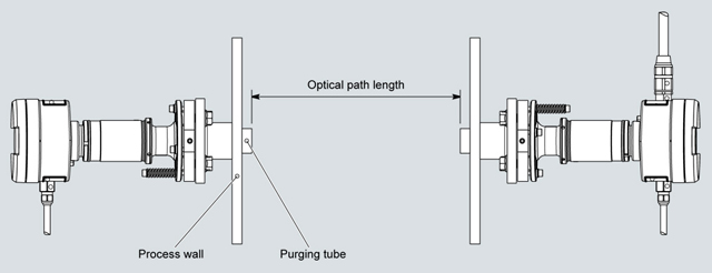
Measurement of the optical path length between the ends of the purging gas tubes
The SITRANS SL carries out continuous self-monitoring, and outputs alarms and warnings to indicate maintenance requirements or a system fault. The information is output as plain text on the LUI display, where symbols identify the category and the severity of the fault.
Alarm categories:
Severity:
The two binary (relay) outputs can be configured freely for the alarm output.
The response of the analog outputs in the event of an alarm is configurable; possible actions are:
In addition, the transmission is available as an output variable.
Note
Specific requirements for the measuring point can make the utilization of special sensor equipment necessary. The possibilities for adapting the sensors are:
the SITRANS SL sensors must be accessible from the side. A space of at least 60 cm must be provided next to the SITRANS SL transmitter and detector units in order to facilitate maintenance and servicing.
To fulfill the safety requirements, a space of at least 10 cm must be provided around the SITRANS SL to facilitate cooling.
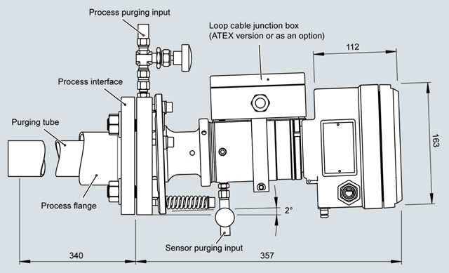
SITRANS SL, transmitter/detector unit (same housing for DN50/PN25 process interface version), dimensions in mm

Connection dimensions of process flanges provided by customer DN50/PN25 and ANSI 4''/150 lbs
Non-EEx version: connection cable - customer interface
Terminal block in the receiver enclosure | Function/voltage | Ethernet cable | ||
|---|---|---|---|---|
1 | + | Power supply | ||
2 | - | |||
3 | Normally closed under power4) | Binary output 0 (relay) | ||
4 | ||||
5 | Normally closed under power4) | Binary output 1 (relay) | ||
6 | ||||
7 | + | Binary input 0 | ||
8 | - | |||
9 | + | Analog output 0 (measurement) | ||
10 | - | |||
11 | + | Analog output 1 (measurement) | ||
12 | - | |||
13 | PROFIBUS A line (RxD/TxD_N - data inverted) | Modbus D1 (RxD/TxD_N - data inverted) | RS 485 -7 ... +12 V DC | |
14 | PROFIBUS B line (RxD/TxD_P - data not inverted) | Modbus D0 (RxD/TxD_P - data not inverted) | ||
15 | PROFIBUS/Modbus shield | |||
16 | Tx+ | Ethernet5) | White/orange | |
17 | Tx- | Orange | ||
18 | Rx+ | White/green | ||
19 | Rx- | Green | ||
20 | + | Analog input 0 (temperature) | ||
21 | - | |||
22 | + | Analog input 1 (pressure) | ||
23 | - | |||
24 | Grounding | |||
25 | Grounding | |||
Ground | Grounding | |||
Ground | Grounding | Shielding | ||
1) This is the maximum power consumption of the SITRANS SL
2) These are the maximum input values
3) These are the maximum output values
4) Note:
"Normal operation" stands for normal operation of the analyzer. The system is connected to the voltage source and is running without problems; no error message generated or displayed.
"Normal under power" refers to the status of the relay under the above-named normal operation. The relay contact of the alarm signal is closed.
5) We recommend that the Ethernet connection is not made via the cable to the Ethernet terminals in the detector unit. Instead, the Ethernet connection should be made via the sensor cable connection set which is optionally available for the detector unit.
Examples of digital output and analog output
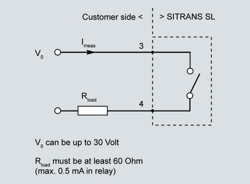
Example of digital output 0
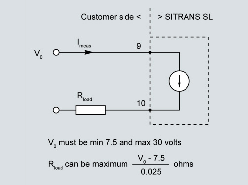
Example of analog output 0,
caution: please note that an external isolating power supply may be required!
Sensor cable terminal box on the receiver side (ATEX version)
Terminal strip in terminal box | Function | Color code | |
|---|---|---|---|
1 | + | 24 V DC voltage supply | Red |
2 | - | Blue | |
3 | Com + | Communication with transmitter | Pink |
4 | Com - | Gray | |
5 | Sync + | Synchronization with transmitter | White |
6 | Sync - | Brown | |
7 | NC | Not used | - |
8 | Tx+ | Ethernet | Gray/pink |
9 | Tx- | Red/blue | |
10 | Rx+ | Black | |
11 | Rx- | Violet | |
PE terminal | - | Grounding | Green |
PE terminal | Grounding | Yellow | |
Gland | Grounding | Shielding | |
The SITRANS SL sensor alignment kit includes a battery-operated lamp, a centering aid with crosshair, and two hook spanners for loosening the sensors from the flange connection plates.
Please note:
The SITRANS SL sensor alignment kit is not explosion-protected! Therefore it must never be used in a hazardous area without approval by the plant operator!
The SITRANS SL has already been factory-calibrated. If it is desirable or necessary to check the calibration, this can be performed using an external calibration test kit following removal of the transmitter and detector units. This procedure has no influence on the optical adjustment of the unit since the flange connection plates remain mounted on the customer flange. The calibration test kit for O2 consists of a stainless steel calibration tube and a thermometer. To carry out the calibration, it is mounted between the transmitter and receiver. The calibration tube for O2 can then be filled with air or a calibration gas.
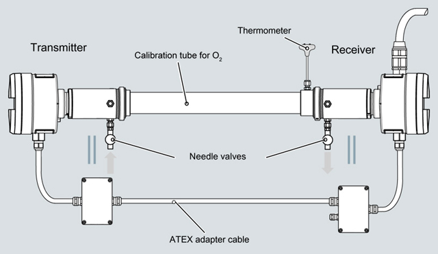
Calibration setup of SITRANS SL O2
| Код | Заказной номер | Описание | Вес (кг) | Заказать |
|---|---|---|---|---|
| 117349 | 7MB6221-.....-.... | sitrans sl in-situ gas analyzer field device sensor pair (cross duct) incl. remote control | 30 | Заказать |
| 78193 | A5E01000694 | calibration verification kit o2 sitrans sl | 1.1 | Заказать |
| 78194 | A5E01000740 | sensor alignment kit sitrans sl | 1.1 | Заказать |
| 78203 | A5E01009881 | process interface for customer flange size: dn50/pn10-40 | 20 | Заказать |
| 124656 | A5E01009883 | process interface for customer flange size: ansi 4" / 150 lbs | 20 | Заказать |
| 78204 | A5E01009892 | purging tube 340 mm (spare part) | 0.01 | Заказать |
| 78205 | A5E01009897 | window lid for receiver unit sitrans sl | 0.5 | Заказать |
| 124659 | A5E01010033 | clamp ring for sitrans sl | 1 | Заказать |
| 124761 | A5E01267567 | junction box ex-e for 25 core communication cable sitrans sl | 2.35 | Заказать |
| 78353 | A5E01714061 | uv cable protector, nom. dia = 48mm, per 30 m length | 9 | Заказать |
| 124796 | A5E02091214 | remote control for sitrans sl, is, csa, fm, atex proof | 0.2 | Заказать |
| 124797 | A5E02091532 | junction box ex e 7 cores (spare part) | 0.5 | Заказать |
| 78372 | A5E02183375 | capillary kit spare part) | 0.5 | Заказать |
| 78512 | A5E02522036 | gasket klinger psm 15010 / dn50 pn16 | 0.1 | Заказать |
| 124939 | A5E02528048 | loop cable set sitrans sl, length: 10 m | 3.3 | Заказать |
| 124940 | A5E02528052 | loop cable set sitrans sl, length: 25 m | 4.7 | Заказать |
| 78524 | A5E02568437 | lid machined unit (spare part) sitrans sl | 1.35 | Заказать |
| 78525 | A5E02568457 | cable gland kit (spare part) sitrans sl | 1 | Заказать |
| 124951 | A5E02568463 | transmitter junction box kit sitrans sl | 1.4 | Заказать |
| 78526 | A5E02568465 | receiver junction box kit | 1.2 | Заказать |
| 124952 | A5E02569944 | needle valve kit (spare part) | 1.1 | Заказать |
| 124953 | A5E02571180 | loop cable 5m (r1.1 spare part) | 0.65 | Заказать |
| 78527 | A5E02571184 | loop cable 10m (r1.1 spare part) | 1.3 | Заказать |
| 78528 | A5E02571186 | loop cable 25m (r1.1 spare part) | 3.25 | Заказать |
| 78537 | A5E02608594 | connection cable profibus ex (spare part) | 1.75 | Заказать |
| 78538 | A5E02608597 | connection cable analog ex (spare part) | 1.45 | Заказать |
| 78588 | A5E02789535 | gasket for ansi 4'' 150 lbs | 0.25 | Заказать |
| 78626 | A5E03328473 | connection cable set, profibus dp (for non-ex sitrans sl) | 3 | Заказать |
| 78627 | A5E03328474 | connection cable set, analog (for non-ex sitrans sl) | 3 | Заказать |
