Different requirements need different transmitters.
With different connection options and different housings - with or without a display.
Whether operation is conventional, smart or through WirelessHART, PROFIBUS PA or FOUNDATION Fieldbus - SITRANS P offers extensive user-friendliness and outstanding performance.
The following pages show examples of typical measuring setups for using SITRANS P pressure transmitters with and without remote seals.
Installation
Remote seals of sandwich design are fitted between the connection flange of the measuring point and a dummy flange.
Remote seals of flange design are fitted directly on the connection flange of the measuring point.
The respective pressure rating of the dummy flange or the flanged remote seal must be observed.
The pressure transmitter should always be installed below the connection flange (and always below the lower connection flange in the case of differential pressure transmitters). When measuring at pressures above atmospheric, the pressure transmitter can also be installed above the connection flange. When measuring at pressures below atmospheric, the transmitter must always be installed below the connection flange (and always below the lower connection flange in the case of differential pressure transmitters).
Offset of measuring range
If there is a difference in height between the two connection flanges when measuring with two remote seals, an additional differential pressure will result from the oil filling of the remote seal capillaries. This results in a measuring range offset which has to be taken into account when you set the pressure transmitter.
An offset of the measuring range also arises when pressure transmitters and remote seals are not installed at the same height
Pressure transmitter output
If the level, separation layer or density increase in closed vessels, the differential pressure and hence the output signal of the pressure transmitter also increase.
If the output signal is to fall as the differential pressure rises, you must swap the start of scale with the end of scale.
With open vessels, a rising pressure is usually assigned to an increasing level, separation layer or density.
Influence of ambient temperature
The capillaries between the remote seal and the pressure transmitter should be kept as short as possible to obtain a good transmission response. Steps should also be taken to avoid temperature differences between the individual remote seals.
If the complete setup is exposed to temperature variations, temperature errors will result from the thermally induced change of volume of the filling liquid in the capillaries, in the remote seals and in the connection parts.
Notes
When measuring separation layers, ensure that:
Possible combinations of pressure transmitters and remote seals
Type of installation | Pressure transmitters | Remote seals |
|---|---|---|
A / B |
|
|
C1 / C2 |
|
(vacuum-proof design in each case) |
|
| |
D |
|
|
E |
|
|
G / H / J |
|
|
Types of installation for pressure and level measurements (open vessels)
Installation type A | ||
|---|---|---|
 | Start-of-scale: | pMA = ÏFL · g · HU - Ïoil · g · H1 |
Full-scale: | pME = ÏFL · g · HO - Ïoil · g · H1 | |
Installation type B | ||
Start-of-scale: | pMA = ÏFL · g · HU + Ïoil · g · H1 | |
Full-scale: | pME = ÏFL · g · HO + Ïoil · g · H1 | |
Legend | ||
pMA | Pressure to be set at start-of-scale | |
pME | Pressure to be set at end-of-scale | |
ÏFL | Density of medium in vessel | |
Ïoil | Density of filling oil in the capillary to the remote seal | |
g | Local acceleration due to gravity | |
HU | Minimum level | |
HO | Maximum level | |
H1 | Distance between vessel flange and pressure transmitter | |
Types of installation for absolute level measurements (closed vessels)
Installation type C1 and C2 | ||
|---|---|---|
 | Start-of-scale: | pMA = pSTART + Ïoil · g · H1 |
Full-scale: | pME = pEND + Ïoil · g · H1 | |
Legend | ||
pMA | Pressure to be set at start-of-scale | |
pME | Pressure to be set at end-of-scale | |
pSTART | Pressure at start-of-scale | |
pEND | Pressure at end-of-scale | |
Ïoil | Density of filling oil in the capillary to the remote seal | |
g | Local acceleration due to gravity | |
H1 | Distance between vessel flange and pressure transmitter | |
Types of installation for differential pressure and flow measurements
Installation type D | ||
|---|---|---|
 | Start-of-scale: | pMA = pSTART - Ïoil · g · HV |
Full-scale: | pME = pEND - Ïoil · g · HV | |
Legend | ||
pMA | Pressure to be set at start-of-scale | |
pME | Pressure to be set at end-of-scale | |
pSTART | Pressure at start-of-scale | |
pEND | Pressure at end-of-scale | |
Ïoil | Density of filling oil in the capillary to the remote seal | |
g | Local acceleration due to gravity | |
HV | Distance between spigots | |
Types of installation for level measurements
Installation type E | ||
|---|---|---|
 | Start-of-scale: | pMA = pFL · g · HU - Ïoil · g · HV |
Full-scale: | pME = pFL · g · HO - Ïoil · g · HV | |
Legend | ||
pMA | Pressure to be set at start-of-scale | |
pME | Pressure to be set at end-of-scale | |
pFL | Density of medium in vessel | |
Ïoil | Density of filling oil in the capillary to the remote seal | |
g | Local acceleration due to gravity | |
HU | Minimum level | |
HO | Maximum level | |
HV | Distance between spigots | |
Installation types G, H and J | ||
|---|---|---|
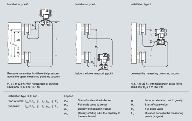 | Start-of-scale: | pMA = pFL · g · HU - Ïoil · g · HV |
Full-scale: | pME = pFL · g · HO - Ïoil · g · HV | |
Legend | ||
pMA | Pressure to be set at start-of-scale | |
pME | Pressure to be set at end-of-scale | |
pFL | Density of medium in vessel | |
Ïoil | Density of filling oil in the capillary to the remote seal | |
g | Local acceleration due to gravity | |
HU | Minimum level | |
HO | Maximum level | |
HV | Distance between spigots | |
The following types of installation are used to measure level, separation level and density in open and closed vessels without the application of remote seals.
Notes
When measuring separation layers, ensure that:
When measuring density, ensure that:
At the end of this section is a questionnaire which you can use is used for hydrostatic level measurements, e.g. for measuring the level in steam boilers, steam drums, condensation vessels, etc.
Setup for pressure transmitters for differential pressure, flange mounting (open vessels)
Level measurement | ||
|---|---|---|
 | Start-of-scale: | pMA = Ï · g · HU |
Full-scale: | pME = Ï · g · HO | |
Legend | ||
pMA | Pressure to be set at start-of-scale | |
pME | Pressure to be set at end-of-scale | |
Ï | Density of medium in vessel | |
g | Local acceleration due to gravity | |
HU | Minimum level | |
HO | Maximum level | |
Separation layer measurement | ||
|---|---|---|
 | Start-of-scale: | pMA = g · (HU · Ï1 + (HO - HU) · Ï2) |
Full-scale: | pME = Ï1 · g · HO | |
Legend | ||
pMA | Pressure to be set at start-of-scale | |
pME | Pressure to be set at end-of-scale | |
Ï1 | Density of the heavier liquid | |
Ï2 | Density of the lighter liquid | |
g | Local acceleration due to gravity | |
HU | Minimum level | |
HO | Maximum level | |
Density measurement | ||
|---|---|---|
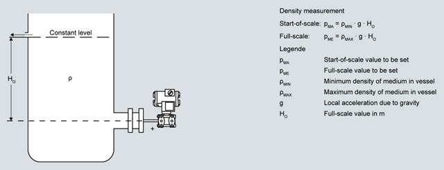 | Start-of-scale: | pMA = ÏMIN · g · HO |
Full-scale: | pME = ÏMAX · g · HO | |
Legend | ||
pMA | Pressure to be set at start-of-scale | |
pME | Pressure to be set at end-of-scale | |
ÏMIN | Minimum density of medium in vessel | |
ÏMAX | Maximum density of medium in vessel | |
g | Local acceleration due to gravity | |
HO | Maximum level | |
Setup for pressure transmitters for differential pressure, flange mounting (closed vessels)
Level measurement, version 1 | ||
|---|---|---|
 | Start-of-scale: | ΔpMA = Ï · g · HU |
Full-scale: | ΔpME = Ï · g · HO | |
Legend | ||
ΔpMA | Pressure to be set at start-of-scale | |
ΔpME | Pressure to be set at end-of-scale | |
Ï | Density of medium in vessel | |
g | Local acceleration due to gravity | |
HU | Minimum level | |
HO | Maximum level | |
Level measurement, version 2 | ||
|---|---|---|
 | Start-of-scale: | pMA = g · (HU · Ï - HV · Ï′) |
Full-scale: | pME = g · (HO · Ï - HV · Ï′) | |
Legend | ||
pMA | Pressure to be set at start-of-scale | |
pME | Pressure to be set at end-of-scale | |
Ï | Density of medium in vessel | |
Ï′ | Density of liquid in the negative pressure line, corresponding to the temperature existing there | |
g | Local acceleration due to gravity | |
HU | Minimum level | |
HO | Maximum level | |
HV | Distance between spigots | |
Separation layer measurement | ||
|---|---|---|
 | Start-of-scale: | ΔpMA = g · (HU · Ï1 + (HO-HU) · Ï2 - HV · Ï′2) |
Full-scale: | ΔpMA = g · (HO · Ï1 - HV · Ï′2) | |
Legend | ||
pMA | Pressure to be set at start-of-scale | |
pME | Pressure to be set at end-of-scale | |
Ï1 | Density of heavier liquid with separation layer in vessel | |
Ï2 | Density of lighter liquid with separation layer in vessel | |
Ï′2 | Density of liquid in the negative pressure line for separation layer measurement, corresponding to the temperature existing there | |
g | Local acceleration due to gravity | |
HU | Minimum level | |
HO | Maximum level | |
HV | Distance between spigots | |


