The SITRANS P300 is a digital pressure transmitter for relative and absolute pressure. The conventional thread versions are available as process connections, as are flush-mounted versions. A large number of the flush-mounted versions are suitable for food and pharmaceutical applications, and satisfy the EHEDG and 3A hygiene requirements.
The output signal is a load-independent direct current from 4 to 20 mA or a PROFIBUS PA or FOUNDATION Fieldbus signal, which is linearly proportional to the input pressure. Communication is via HART protocol or PROFIBUS PA or FOUNDATION Fieldbus interface. The basic settings of the pressure transmitter can be made easily on-site by means of three buttons.
The SITRANS P300 has a single-chamber stainless steel casing. The pressure transmitter is approved with "intrinsically safe" type of protection. It can be used in zone 1 or zone 0.
The pressure transmitter is available in versions for gauge pressure and for absolute pressure. The output signal is always a load-independent direct current from 4 to 20 mA or a PROFIBUS PA or FOUNDATION Fieldbussignal, which is linearly proportional to the input pressure. The pressure transmitter measures aggressive, non-aggressive and hazardous gases, as well as vapors and liquids.
It can be used for the following measurement types:
With appropriate parameter settings, it can also be used for the following additional measurement types:
The "intrinsically-safe" EEx version of the transmitter can be installed in hazardous areas (zone 1). The transmitters are provided with an EC type examination certificate and comply with the respective harmonized European standards of ATEX.
This variant measures aggressive, non-aggressive and hazardous gases, vapors and liquids.
The smallest span is 0.01 bar g (0.15 psi g), the largest is 400 bar g (5802 psi g).
With appropriate parameter settings, the gauge pressure variant measures the level of aggressive, non-aggressive and hazardous liquids.
For measuring the level in an open container you require one device; for measuring the level in a closed container, you require two devices and a process control system.
This variant measures the absolute pressure of aggressive, non-aggressive and hazardous gases, vapors and liquids.
The smallest span is 0.008 bar a (0.12 psi a), the largest is 30 bar a (435 psi a)).
SITRANS P300 for gauge and absolute pressure | ||||||
|---|---|---|---|---|---|---|
HART | PROFIBUS PA and FOUNDATION Fieldbus | |||||
Gauge pressure input | ||||||
Measured variable | Gauge pressure | |||||
Spans (infinitely adjustable) or nominal measuring range and | Span (min. ... max.) | Max. perm. test pressure | Nominal measuring range | Max. perm. test pressure | ||
0.01 ... 1 bar g | 6 bar g | 1 bar g | 6 bar g | |||
0.04 ... 4 bar g | 10 bar g | 4 bar g | 10 bar g | |||
0.16 ... 16 bar g | 32 bar g | 16 bar g | 32 bar g | |||
0.6 ... 63 bar g | 100 bar g | 63 bar g | 100 bar g | |||
1.6 ... 160 bar g | 250 bar g | 160 bar g | 250 bar g | |||
4.0 ... 400 bar g | 600 bar g | 400 bar g | 600 bar g | |||
Depending on the process connection, the span may differ from these values | Depending on the process connection, the nominal measuring range may differ from these values | |||||
Lower measuring limit | ||||||
| 30 mbar a (0.44 psi a) | |||||
Upper measuring limit | ||||||
| 100% of max. span | 100 % of the max. nominal measuring range | ||||
Absolute pressure input | ||||||
Measured variable | Absolute pressure | |||||
Spans (infinitely adjustable) or nominal measuring range and | Span (min. ... max.) | Max. perm. test pressure | Nominal measuring range | Max. perm. test pressure | ||
8 ... 250 mbar a | 6 bar a | 250 mbar a | 6 bar a | |||
43 ... 1300 mbar a | 10 bar a | 1.30 bar a | 10 bar a | |||
0.16 ... 5 bar a | 30 bar a | 5 bar a | 30 bar a | |||
1 ... 30 bar a | 100 bar a | 30 bar a | 100 bar a | |||
Lower measuring limit | ||||||
| 0 mbar a (0 psi a) | |||||
Upper measuring limit | ||||||
| 100% of max. span | 100 % of the max. nominal measuring range | ||||
Input of gauge pressure, with flush-mounted diaphragm | ||||||
Measured variable | Gauge pressure, flush-mounted | |||||
Spans (infinitely adjustable) or nominal measuring range and max. permissible test pressure | Span (min. ... max.) | Max. perm. test pressure | Nominal measuring range | Max. perm. test pressure | ||
0,01 ... 1 bar g (0.15 ... 14.5 psi g) | 6 bar g | 1 bar g | 6 bar g | |||
0,04 ... 4 bar g (0.58 ... 58 psi g) | 10 bar g | 4 bar g | 10 bar g | |||
0,16 ... 16 bar g (2.32 ... 232 psi g) | 32 bar g | 16 bar g | 32 bar g | |||
0,6 ... 63 bar g (9.14 ... 914 psi g) | 100 bar g | 63 bar g | 100 bar g | |||
Lower measuring limit | 100 mbar a (1.45 psi a) | |||||
Upper measuring limit | ||||||
| 100% of max. span | 100 % of the max. nominal measuring range | ||||
Input of absolute pressure, with flush-mounted diaphragm | ||||||
Measured variable | Absolute pressure, flush-mounted | |||||
Spans (infinitely adjustable) or nominal measuring range and | Span (min. ... max.) | Max. perm. test pressure | Nominal measuring range | Max. perm. test pressure | ||
43 ... 1300 mbar a | 10 bar a | 1300 mbar a | 10 bar a | |||
0.16 ... 5 bar a | 30 bar a | 5 bar a | 30 bar a | |||
1 ... 30 bar a | 100 bar a | 30 bar a | 100 bar a | |||
Depending on the process connection, the span may differ from these values | Depending on the process connection, the nominal measuring range may differ from these values | |||||
Lower measuring limit | 0 bar a (0 psi a) | |||||
Upper measuring limit | ||||||
| 100% of max. span | 100 % of the max. nominal measuring range | ||||
Output | ||||||
Output signal | 4 ... 20 mA | Digital PROFIBUS PA signal | ||||
Physical bus | - | IEC 61158-2 | ||||
Protection against polarity reversal | Protected against short-circuit and polarity reversal. Each connection against the other with max. supply voltage. | |||||
Electrical damping (step width 0.1 s) | Set to 2 s (0 ... 100 s) | |||||
Measuring accuracy | According to IEC 60770-1 | |||||
Reference conditions | Rising characteristic curve, start-of-scale value 0 bar, stainless steel seal diaphragm, measuring cell with silicone oil, room temperature 25 °C (77 °F), span ratio (r = max. span / set span) | |||||
Error in measurement at limit setting incl. hysteresis and reproducibility | ||||||
Gauge pressure | Absolute pressure | Absolute pressure, flush-mounted | Gauge pressure | Absolute pressure | Absolute pressure, flush-mounted | |
Linear characteristic | ≤ 0,075 % | ≤ 0,1 % | ≤ 0,2 % | |||
| ≤ (0.0029 · r + 0.071) % | ≤ 0,1 % | ≤ 0,2 % | |||
| ≤ (0.0045 · r + 0.071) % | ≤ 0,2 % | ≤ 0,4 % | |||
| ≤ (0.005 · r + 0.05) % | - | - | |||
Step response time T63 | approx. 0.2 NO | |||||
Long-term stability at ± 30 °C (± 54 °F) | ≤ (0.25 · r) %/5 years | ≤ (0.1 · r) %/year | ≤ 0.25 %/5 years | ≤ 0.1 %/year | ||
Influence of ambient temperature | ||||||
| ≤ (0.08· r + 0.1) % | ≤ (0.2 · r + 0.3) % | ≤ 0,3 % | ≤ 0,5 % | ||
Conversion of temperature error per 28 °C. Valid for temperature range -3 ... +53 °C < (0.064 . r + 0.08) % / 28 °C (50 °F). | ||||||
| ≤ (0.1 · r + 0.15) %/10 K | ≤ (0.2 · r + 0.3) %/10 K | ≤ 0.25 %/10 K | ≤ 0.5 %/10 K | ||
Influence of the medium temperature (only with flush-mounted diaphragm) | ||||||
| 3 mbar/10 K (0.04 psi/10 K) | |||||
Rated conditions | ||
|---|---|---|
Installation conditions | ||
Ambient temperature | Observe the temperature class in areas subject to explosion hazard. | |
| -40 ... +85 °C (-40 ... +185 °F) | |
| -10 ... +85 °C (14 ... +185 °F) | |
| -20 ... +85 °C (-4 ... +185 °F) | |
| -30 ... +85 °C (-22 ... +185 °F) | |
| -50 ... +85 °C (-58 ... +185 °F) | |
Climatic class | ||
Condensation | Relative humidity 0 ... 100 % | |
Degree of protection acc. to EN 60529 | IP65, IP68, NEMA X, enclosure cleaning, resistant to lyes, steam to 150 °C (302 °F) | |
Electromagnetic Compatibility | ||
| Acc. to EN 61326 and NAMUR NE 21 | |
Medium conditions | ||
Temperature of medium | ||
| -40 ... +100 °C (-40 ... +212 °F) | |
| -40 ... +150 °C (-40 ... +302 °F) | |
| -10 ... +150 °C (-14 ... +302 °F) | |
| -40 ... +200 °C (-40 ... +392 °F) | |
| -20 ... +100 °C (-4 ... +212 °F) | |
| -10 ... +250 °C (14 ... 482 °F) | |
Design (standard version) | ||
Weight (without options) | Approx. 800 g (1.8 lb) | |
Enclosure material | Stainless steel, mat. no. 1.4301/304 | |
Material of parts in contact with the medium | ||
| Stainless steel, mat. no. 1.4404/316L or Hastelloy C276, mat. no. 2.4819 | |
| Stainless steel, mat. no. 1.4404/316L | |
| Stainless steel, mat. no. 1.4404/316L or Hastelloy C276, mat. no. 2.4819 | |
|
| |
Process connection |
| |
Design (version with flush-mounted diaphragm) | ||
Weight (without options) | approx. 1 ... 13 kg (2.2 ... 29 lb) | |
Enclosure material | Stainless steel, mat. no. 1.4301/304 | |
Material of parts in contact with the medium | ||
| Stainless steel, mat. no. 1.4404/316L | |
| Stainless steel, mat. no. 1.4404/316L | |
|
| |
Process connection |
| |
Surface quality touched-by-media | Ra-values ≤ 0.8 µm (32 µ-inch)/welds Ra) ≤ 1.6 µm (64 µ-inch) (Process connectionsaccording to 3A; Ra-values ≤ 0.8 µm (32 µ-inch)/welds Ra) ≤ 0.8 µm (32 µ-inch) | |
Power supply UH | ||
Terminal voltage on transmitter | 10.5 ... 42 V DC | Supplied through bus |
Separate power supply | - | Not necessary |
Bus voltage | ||
| - | 9 ... 32 V |
| - | 9 ... 24 V |
Current consumption | ||
| - | 12.5 mA |
| - | Yes |
| - | 15.5 mA |
Fault disconnection electronics (FDE) | - | Available |
Certificates and approvals | ||
Classification according to PED 97/23/EC | For gases of fluid group 1 and liquids of fluid group 1; complies with requirements of Article 3, paragraph 3 (sound engineering practice) | |
Water, waste water | In preparation | |
Explosion protection | ||
Intrinsic safety "i" | PTB 05 ATEX 2048 | |
| Ex II 1/2 G EEx ia/ib IIB/IIC T4, T5, T6 | |
| ||
| -40 ... +85 °C (-40 ... +185 °F) | |
| -40 ... +70 °C (-40 ... +158 °F) | |
| -40 ... +60 °C (-40 ... +140 °F) | |
| To certified intrinsically-safe circuits with peak values: Ui = 30 V, Ii = 100 mA, | To certified intrinsically-safe circuits with peak values: FISCO supply unit: Ui = 17.5 V, Ii = 380 mA, Linear barrier: Ui = 24 V, Ii = 250 mA, Pi = 1.2 W |
| Ci = 6 nF | Ci = 1.1 nF |
| Li = 0.4 mH | Li ≤ 7 μH |
Explosion protection to FM for USA and Canada (cFMUS) | ||
| Certificate of Compliance 3025099 CL I, DIV 1, GP ABCD T4 ... T6; CL II, DIV 1, GP EFG; CL III; CL I, ZN 0/1 AEx ia IIC T4 ... T6; CL I, DIV 2, GP ABCD T4 ... T6; CL II, DIV 2, GP FG; CL III | |
| Certificate of Compliance 3025099C CL I, DIV 1, GP ABCD T4 ... T6; CL II, DIV 1, GP EFG; CL III; Ex ia IIC 4 ... T6; CL I, DIV 2, GP ABCD T4 ... T6; CL II, DIV 2, GP FG; CL III | |
Dust explosion protection for zone 20/21/22 | PTB 05 ATEX 2048 | |
| Ex II 1D Ex ia D 20 T 120 °C Ex II 2D Ex ib D 21 T 120 °C Ex II 3D Ex ib D 21 T 120 °C | |
| ||
| -40 ... +85 °C (-40 ... +185 °F) (in the case of mineral glass windows only | |
| -40 ... +70 °C (-40 ... +158 °F) (in the case of mineral glass windows only | |
| -40 ... +60 °C (-40 ... +140 °F) (in the case of mineral glass windows only | |
| To certified intrinsically-safe circuits with peak values: Ui = 30 V, Ii = 100 mA, Pi = 750 mW | To certified intrinsically-safe circuits with peak values: Ui = 24 V, Ii = 380 mA, Pi = 5.32 W |
| Ci = 6 nF | Ci = 5 nF |
| Li ≤ 0.4 μH | Li = 10 μH |
Type of protection Ex nA/nL/ic (Zone 2) | PTB 05 ATEX 2048 | |
| II 2/3 G Ex ic IIB/IIC T4/T5/T6 II 2/3 G Ex nA T4/T5/T6 II 2/3 G Ex nL IIB/IIC T4/T5/T6 | |
| ||
| -40 ... +85 °C (-40 ... +185 °F) (in the case of mineral glass windows only -20 ... +85 °C (-4 ... +185 °F)) | |
| -40 ... +70 °C (-40 ... +158 °F) (in the case of mineral glass windows only -20 ... +70 °C (-4 ... +158 °F)) | |
| -40 ... +60 °C (-40 ... +140 °F) (in the case of mineral glass windows only -20 ... +60 °C (-4 ... +140 °F)) | |
| To certified intrinsically-safe circuits with peak values: Um = 45 V | To certified intrinsically-safe circuits with peak values: Um = 32 V |
| To certified intrinsically-safe circuits with peak values: Ui = 45 V | To certified intrinsically-safe circuits with peak values: Ui = 32 V |
| Ci = 6 nF | Ci = 5 nF |
| Li = 0.4 mH | Li = 20 μH |
HART communication | |
|---|---|
HART communication | 230 ... 1100 Ω |
Protocol | HART Version 5.x |
Software for computer | SIMATIC PDM |
PROFIBUS PA communication | |
|---|---|
Simultaneous communication with master class 2 (max.) | 4 |
The address can be set using | Configuration tool or local operation (standard setting Address 126) |
Cyclic data usage | |
| 5 (one measured value) or 10 (two measured values) |
| 0, 1 or 2 (totalizer mode and reset function for dosing) |
| |
Device profile | PROFIBUS PA Profile for Process Control Devices Version 3.0, Class B |
Function blocks | 2 |
| |
| Yes, linearly rising or falling characteristic |
| 0 … 100 s |
| Input /Output |
| parameterizable (last good value, substitute value, incorrect value) |
| Yes, one upper and lower warning limit and one alarm limit respectively |
| Can be reset, preset, optional direction of counting, simulation function of register output |
| parameterizable (summation with last good value, continuous summation, summation with incorrect value) |
| One upper and lower warning limit and one alarm limit respectively |
| 1 |
Transducer blocks | 2 |
| |
| Yes |
| Yes |
| Max. 30 nodes |
| Constant value or over parameterizable ramp function |
FOUNDATION Fieldbus communication | |
|---|---|
Function blocks | 3 function blocks analog input, 1 function block PID |
| |
| Yes, linearly rising or falling characteristic |
| 0 & 100 s |
| Output/input (can be locked within the device with a bridge) |
| parameterizable (last good value, substitute value, incorrect value) |
| Yes, one upper and lower warning limit and one alarm limit respectively |
| Yes |
| Standard FOUNDATION Fieldbus function block |
| 1 resource block |
Transducer blocks | 1 transducer block Pressure with calibration, 1 transducer block LCD |
| |
| Yes |
| Yes |
| Constant value or over parameterizable ramp function |
The device comprises:

Perspective view of SITRANS P300
The housing has a screw-on cover (5) and, depending on the version, is with or without an inspection window. The electrical terminal housing, the buttons for operation of the device are located under this cover and, depending on the version, the digital display. The connections for the auxiliary power UH and the shield are in the terminal housing. The cable gland is mounted on the side of the housing. The measuring cell with the process connection (2) is located on the bottom of the housing. The measuring cell with the process connection may differ from the one shown in the diagram, depending on the device version.


Function diagram of electronics
The input pressure is converted into an electrical signal by the sensor (1). This signal is amplified by the measuring amplifier (2) and digitalized in an analog-to-digital converter (3). The digital signal is analyzed in a microcontroller (4) and corrected according to linearity and thermal characteristics. In a digital-to-analog converter (5) it is then converted into the output current of 4 to 20 mA. A diode circuit provides reverse polarity protection. You can make an uninterrupted current measurement with a low-ohm ammeter at the connection (10). The data specific to the measuring cell, the electronic data and parameter settings are stored in two non-volatile memories (6). The first memory is linked to the measuring cell, the second to the electronics.
The buttons (8) can be used to call up individual functions, so-called modes. If you have a device with a display (9), you can use this to track mode settings and other messages. The basic mode settings can be changed with a computer via the HART modem (7).

Function diagram of electronics
The input pressure is converted into an electrical signal by the sensor (1). This signal is amplified by the measuring amplifier (2) and digitalized in an analog-to-digital converter (3). The digital signal is analyzed in a microcontroller (4) and corrected according to linearity and thermal characteristics. It is then made available at the PROFIBUS PA over an electrically isolated PROFIBUS PA interface (7). The data specific to the measuring cell, the electronic data and parameter settings are stored in two non-volatile memories (6). The first memory is linked to the measuring cell, the second to the electronics.
The buttons (8) can be used to call up individual functions, so-called modes. If you have a device with a display (9), you can use this to track mode settings and other messages. The basic mode settings can be changed with a computer over the bus master (12).

Function diagram of electronics
The bridge output voltage created by the sensor (1, Figure "Function diagram of electronics") is amplified by the measuring amplifier (2) and digitized in the analog-to-digital converter (3). The digital information is evaluated in the microcontroller, its linearity and temperature response corrected, and provided on the FOUNDATION Fieldbus through an electrically isolated FOUNDATION Fieldbus interface (7).
The data specific to the measuring cell, the electronics data, and the parameter data are stored in the two non-volatile memories (6). The one memory is coupled to the measuring cell, the other to the electronics. As the result of this modular design, the electronics and the measuring cell can be replaced separately from each other.
Using the three input buttons (8) you can parameterize the pressure transmitter directly at the measuring point. The input buttons can also be used to control the view of the results, the error messages and the operating modes on the display (9).
The results with status values and diagnostic values are transferred by cyclic data transmission on the FOUNDATION Fieldbus. Parameterization data and error messages are transferred by acyclic data transmission. Special software such as National Instruments Configurator is required for this.
The process connections available include the following:
Measuring cell for gauge pressure

Measuring cell for gauge pressure, function diagram
The input pressure (pe) is transferred to the gauge pressure sensor (6) via the seal diaphragm (4) and the filling liquid (5), displacing its measuring diaphragm. The displacement changes the resistance value of the four piezo resistors in the measuring diaphragm in a bridge circuit. The change in the resistance causes a bridge output voltage proportional to the input pressure.
Transmitters with spans ≤ 63 bar ( ≤ 926.1 psi) measure the input pressure compared to atmospheric, transmitters with spans of ≥ 160 bar (≥ 2352 psi) compared to a vacuum.
Measuring cell for absolute pressure

Measuring cell for absolute pressure, function diagram
The input pressure (pe) is transferred to the absolute pressure sensor (5) via the seal diaphragm (3) and the filling liquid (4), displacing its measuring diaphragm. The displacement changes the resistance value of the four piezo resistors in the measuring diaphragm in a bridge circuit. The change in the resistance causes a bridge output voltage proportional to the input pressure.
Measuring cell for gauge pressure, flush-mounted diaphragm

Measuring cell for gauge pressure, flush-mounted diaphragm, function diagram
The input pressure (pe) is transferred to the gauge pressure sensor (6) via the seal diaphragm (4) and the filling liquid (5), displacing its measuring diaphragm. The displacement changes the resistance value of the four piezo resistors in the measuring diaphragm in a bridge circuit. The change in the resistance causes a bridge output voltage proportional to the input pressure.
Transmitters with spans ≤ 63 bar ( ≤ 926.1 psi) measure the input pressure compared to atmospheric, transmitters with spans of ≥ 160 bar (≥ 2352 psi) compared to a vacuum.
Measuring cell for absolute pressure, flush-mounted diaphragm

Measuring cell for absolute pressure, flush-mounted diaphragm, function diagram
The input pressure (pe) is transferred to the absolute pressure sensor (5) via the seal diaphragm (3) and the filling liquid (4), displacing its measuring diaphragm. The displacement changes the resistance value of the four piezo resistors in the measuring diaphragm in a bridge circuit. The change in the resistance causes a bridge output voltage proportional to the input pressure.
Depending on the version, there are a range of options for parameterizing the pressure transmitter and for setting or scanning the parameters.
Parameterization using the input buttons (local operation)
With the input buttons you can easily set the most important parameters without any additional equipment.
Parameterization using HART communication
Parameterization using HART communication is performed with a HART Communicator or a PC.

Communication between a HART Communicator and a pressure transmitter
When parameterizing with the HART Communicator, the connection is made directly to the 2-wire cable.

HART communication between a PC communicator and a pressure transmitter
When parameterizing with a PC, the connection is made through a HART modem.
The signals needed for communication in conformity with the HART 5.x or 6.x protocols are superimposed on the output current using the Frequency Shift Keying (FSK) method.
Adjustable parameters on SITRANS P300 with HART communication
Parameters | Input buttons | HART communication |
|---|---|---|
Start of scale | x | x |
Full-scale value | x | x |
Electrical damping | x | x |
Start-of-scale value without application of a pressure ("Blind setting") | x | x |
Full-scale value without application of a pressure ("Blind setting") | x | x |
Zero adjustment | x | x |
current transmitter | x | x |
Fault current | x | x |
Disabling of buttons, write protection | x | x 1) |
Type of dimension and actual dimension | x | x |
Input of characteristic | x | |
Freely-programmable LCD | x | |
Diagnostic functions | x |
1) Cancel apart from write protection
Diagnostic functions for SITRANS P300 with HART communication
Available physical units of display for SITRANS P300 with HART communication
Table style: Technical specifications 2
Physical variable | Physical dimensions |
Pressure (setting can also be made in the factory) | Pa, MPa, kPa, bar, mbar, torr, atm, psi, g/cm2, kg/cm2, inH2O, inH2O (4 °C), mmH2O, ftH2O (20 °C), inHg, mmHg |
Level (height data) | m, cm, mm, ft, in |
Volume | m3, dm3, hl, yd3, ft3, in3, US gallon, lmp. gallon, bushel, barrel, barrel liquid |
Mass | g, kg, t, lb, Ston, Lton, oz |
Temperature | K, °C, °F, °R |
Miscellaneous | %, mA |
Parameterization through PROFIBUS PA interface
Fully digital communication through PROFIBUS PA, profile 3.0, is particularly user-friendly. The PROFIBUS connects the SITRANS P30 0 PA to a process control system, e. g. SIMATIC PSC 7. Communication is possible even in a potentially explosive environment.
For parameterization through PROFIBUS you need suitable software, e. g. SIMATIC PDM (Process Device Manager)
Parameterization through FOUNDATION Fieldbus interface
Fully digital communication through FOUNDATION Fieldbus is particularly user-friendly. Through the FOUNDATION Fieldbus the P300 is connected to a process control system. Communication is possible even in a potentially explosive environment.
For parameterization through the FOUNDATION Fieldbus you need suitable software, e. g. National Instruments Configurator.
Adjustable parameters for SITRANS P300 PA and FOUNDATION Fieldbus
Adjustable parameters | Input buttons | PROFIBUS PA and FOUNDATION Fieldbus interface |
|---|---|---|
Electrical damping | x | x |
Zero adjustment (correction of position) | x | x |
Buttons and/or function disabling | x | x |
Source of measured-value display | x | x |
Physical dimension of display | x | x |
Position of decimal point | x | x |
Bus address | x | x |
Adjustment of characteristic | x | x |
Input of characteristic | x | |
Freely-programmable LCD | x | |
Diagnostic functions | x |
Diagnostic functions for SITRANS P300 PA and FOUNDATION Fieldbus
Physical dimensions available for the display
Physical variable | Physical dimensions |
Pressure (setting can also be made in the factory) | Mpa, kPa, Pa, bar, mbar, torr, atm, psi, g/cm2, kg/cm2, mmH2O, mmH2O (4 °C), inH2O, inH20 (4 °C), ftH2O (20 °C), mmHg, inHg |
Level (height data) | m, cm, mm, ft, in, yd |
Mass | g, kg, t, lb, Ston, Lton, oz |
Volume | m3, dm3, hl, yd3, ft3, in3, US gallon, lmp. gallon, bushel, barrel, barrel liquid |
volume flow | m3/s, m3/min, m3/h, m3/d, l/s, l/min, l/h, l/ d, Ml/d, ft3/s, ft3/min, ft3/h, ft3/d, US gallon/s, US gallon/min, US gallon/h, US gallon/d, bbl/s, bbl/min, bbl/h, bbl/d |
Mass flow | g/s, g/min, g/h, g/d, kg/s, kg/min, kg/h, kg/d, t/s, t/min, t/h, /t/d, lb/s, lb/min, lb/h, lb/d, STon/s, STon/min, STon/h, STon/d, LTon/s, LTon/min, LTon/h, LTon/d |
Total mass flow | t, kg, g, lb, oz, LTon, STon |
Temperature | K, °C, °F, °R |
Miscellaneous | % |
Hygiene version
In the case of the SITRANS P300 with 7MF812.-... flush-mounted diaphragm, selected connections comply with the requirements of the EHEDG or 3A. You will find further details in the order form. Please note in particular that the seal materials used must comply with the requirements of 3A. Similarly, the filling liquids used must be FDA-compliant.

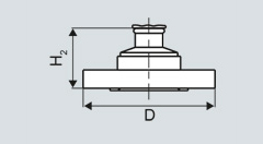
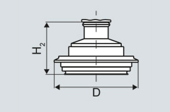
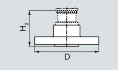
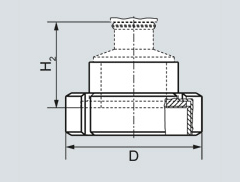
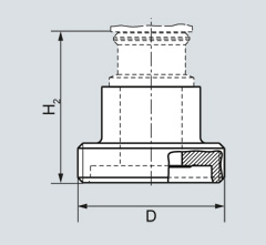
SITRANS P300, with oval flange, dimensions in mm (inch)

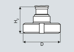
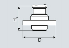
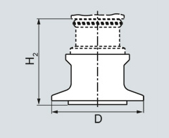
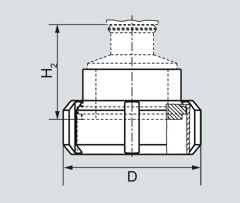
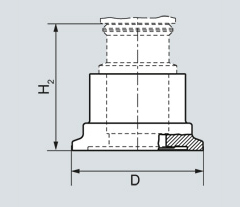
SITRANS P300, process connection M20 x 1.5, with mounted mounting bracket, dimensions in mm (inch)

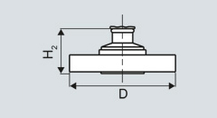
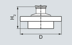
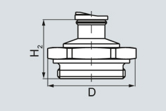
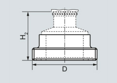
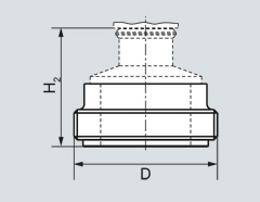
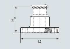
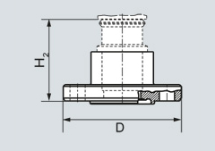
SITRANS P300, flush-mounted, dimensions in mm (inch)
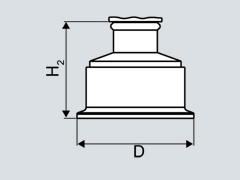
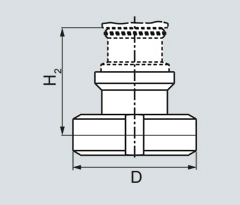
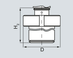
The diagram shows a SITRANS P300 with an example of a flange. In this drawing the height is subdivided into H1 and H2.
H1 = Height of the SITRANS P300 up to a defined cross-section
H2 = Height of the flange up to this defined cross-section
Only the height H2 is indicated in the dimensions of the flanges.
Flange to EN
EN 1092-1 | ||||
|---|---|---|---|---|
|
| DN | PN | ∅D | H2 |
25 | 40 | 115 mm (4.5") | Approx. 52 mm (2") | |
25 | 100 | 140 mm (5.5") | ||
40 | 40 | 150 mm (5.9") | ||
40 | 100 | 170 mm (6.7") | ||
50 | 16 | 165 mm (6.5") | ||
50 | 40 | 165 mm (6.5") | ||
80 | 16 | 200 mm (7.9") | ||
80 | 40 | 200 mm (7.9") | ||
Flanges to ASME
ASME B16.5 | ||||
|---|---|---|---|---|
|
| DN | Class | ∅D | H2 |
1“ | 150 | 110 mm (4.3") | Approx. 52 mm (2") | |
1“ | 300 | 125 mm (4.9") | ||
1½“ | 150 | 130 mm (5.1") | ||
1½“ | 300 | 155 mm (6.1") | ||
2“ | 150 | 150 mm (5.9") | ||
2“ | 300 | 165 mm (6.5") | ||
3“ | 150 | 190 mm (7.5") | ||
3“ | 300 | 210 mm (8.1") | ||
4“ | 150 | 230 mm (9.1") | ||
4“ | 300 | 255 mm (10.0") | ||
Connections to DIN
DIN 11851 (milk pipe union) | ||||
|---|---|---|---|---|
|
| DN | PN | ∅D | H2 |
50 | 25 | 92 mm (3.6") | Approx. 52 mm (2") | |
80 | 25 | 127 mm (5.0") | ||
TriClamp to DIN 32676 | ||||
|---|---|---|---|---|
|
| DN | PN | ∅D | H2 |
50 | 16 | 64 mm (2.5") | Approx. 52 mm (2") | |
65 | 16 | 91 mm (3.6") | ||
Other connections
Varivent connection | ||||
|---|---|---|---|---|
|
| DN | PN | ∅D | H2 |
40 ... 125 | 40 | 84 mm (3.3") | Approx. 52 mm (2") | |
Biocontrol connection | ||||
|---|---|---|---|---|
|
| DN | PN | ∅D | H2 |
50 | 16 | 90 mm (3.5") | Approx. 52 mm (2") | |
65 | 16 | 120 mm (4.7") | ||
Sanitary process connection to DRD | ||||
|---|---|---|---|---|
|
| DN | PN | ∅D | H2 |
50 | 40 | 105 mm (4.1”) | Approx. 52 mm (2") | |
Sanitary process screw connection to NEUMO Bio-Connect | ||||
|---|---|---|---|---|
|
| DN | PN | ∅D | H2 |
50 | 16 | 82 mm (3.2") | Approx. 52 mm (2") | |
65 | 16 | 105 mm (4.1”) | ||
80 | 16 | 115 mm (4.5”) | ||
100 | 16 | 145 mm (5.7") | ||
2” | 16 | 82 mm (3.2") | ||
2½” | 16 | 105 mm (4.1”) | ||
3” | 16 | 105 mm (4.1”) | ||
4” | 16 | 145 mm (5.7") | ||
Sanitary process connection to NEUMO Bio-Connect flange connection | ||||
|---|---|---|---|---|
|
| DN | PN | ∅D | H2 |
50 | 16 | 110 mm (4.3") | Approx. 52 mm (2") | |
65 | 16 | 140 mm (5.5”) | ||
80 | 16 | 150 mm (5.9”) | ||
100 | 16 | 175 mm (6.9") | ||
2” | 16 | 100 mm (3.9") | ||
2½” | 16 | 110 mm (4.3”) | ||
3” | 16 | 140 mm (5.5”) | ||
4” | 16 | 175 mm (6.9") | ||
Sanitary process connection to NEUMO Bio-Connect clamp connection | ||||
|---|---|---|---|---|
|
| DN | PN | ∅D | H2 |
50 | 16 | 77.4 mm (3.0") | Approx. 52 mm (2") | |
65 | 10 | 90.9 mm (3.6") | ||
80 | 10 | 106 mm (4.2") | ||
100 | 10 | 119 mm (4.7") | ||
2” | 16 | 64 mm (2.5") | ||
2½” | 16 | 77.4 mm (3.0”) | ||
3” | 10 | 90.9 mm (3.6”) | ||
4” | 10 | 119 mm (4.7") | ||
Sanitary process connection to NEUMO Bio-Connect S flange connection | ||||
|---|---|---|---|---|
|
| DN | PN | ∅D | H2 |
50 | 16 | 125 mm (4.9") | Approx. 52 mm (2") | |
65 | 10 | 145 mm (5.7") | ||
80 | 10 | 155 mm (6.1") | ||
100 | 10 | 180 mm (7.1") | ||
2” | 16 | 125 mm (4.9") | ||
2½” | 10 | 135 mm (5.3”) | ||
3” | 10 | 145 mm (5.7") | ||
4” | 10 | 180 mm (7.1") | ||
Threaded connection G¾", G1" and G2" acc. to DIN 3852 | ||||
|---|---|---|---|---|
 | DN | PN | ∅D | H2 |
¾“ | 63 | 37 mm (1.5") | approx. 45 mm (1.8") | |
1“ | 63 | 48 mm (1.9") | approx. 47 mm (1.9") | |
2“ | 63 | 78 mm (3.1") | Approx. 52 mm (2") | |
Tank connection TG 52/50 and TG52/150 | ||||
|---|---|---|---|---|
 | DN | PN | ∅D | H2 |
25 | 40 | 63 mm (2.5") | approx. 63 mm (2.5") | |
25 | 40 | 63 mm (2.5") | approx. 170 mm (6.7") | |
SMS socket with union nut | ||||
|---|---|---|---|---|
 | DN | PN | ∅D | H2 |
2“ | 25 | 84 mm (3.3") | Approx. 52 mm (2.1") | |
2½“ | 25 | 100 mm (3.9") | ||
3“ | 25 | 114 mm (4.5") | ||
SMS threaded socket | ||||
|---|---|---|---|---|
 | DN | PN | ∅D | H2 |
2“ | 25 | 70 x 1/6 mm | Approx. 52 mm (2.1") | |
2½“ | 25 | 85 x 1/6 mm | ||
3“ | 25 | 98 x 1/6 mm | ||
IDF socket with union nut | ||||
|---|---|---|---|---|
 | DN | PN | ∅D | H2 |
2“ | 25 | 77 mm (3") | Approx. 52 mm (2.1") | |
2½“ | 25 | 91 mm (3.6") | ||
3“ | 25 | 106 mm (4.2") | ||
IDF threaded socket | ||||
|---|---|---|---|---|
 | DN | PN | ∅D | H2 |
2“ | 25 | 64 mm (2.5") | Approx. 52 mm (2.1") | |
2½“ | 25 | 77.5 mm (3.1") | ||
3“ | 25 | 91 mm (3.6") | ||
Aseptic threaded socket to DIN 11864-1 Form A | ||||
|---|---|---|---|---|
 | DN | PN | ∅D | H2 |
50 | 25 | 78 x 1/6" | Approx. 52 mm (2.1") | |
65 | 25 | 95 x 1/6" | ||
80 | 25 | 110 x ¼" | ||
100 | 25 | 130 x ¼" | ||
Aseptic flange with notch to DIN 11864-2 Form A | ||||
|---|---|---|---|---|
 | DN | PN | ∅D | H2 |
50 | 16 | 94 | Approx. 52 mm (2.1") | |
65 | 16 | 113 | ||
80 | 16 | 133 | ||
100 | 16 | 159 | ||
Aseptic flange with groove to DIN 11864-2 Form A | ||||
|---|---|---|---|---|
 | DN | PN | ∅D | H2 |
50 | 16 | 94 | Approx. 52 mm (2.1") | |
65 | 16 | 113 | ||
80 | 16 | 133 | ||
100 | 159 | |||
Aseptic clamp with groove to DIN 11864-3 Form A | ||||
|---|---|---|---|---|
 | DN | PN | ∅D | H2 |
50 | 25 | 77,5 | Approx. 52 mm (2.1") | |
65 | 25 | 91 | ||
80 | 16 | 106 | ||
100 | 16 | 130 | ||
| Код | Заказной номер | Описание | Вес (кг) | Заказать |
|---|---|---|---|---|
| 117992 | 7MF4997-1DA | hart-модем с интерфесом rs232 для подключения измерительных датчиков с hart-протоколом к компьютеру | 0.1 | Заказать |
| 71484 | 7MF4997-1DB | hart-модем с usb-интерфесом для подключения измерительных датчиков с hart-протоколом к компьютеру | 0.1 | Заказать |
| 71524 | 7MF4997-2HA | сварной разъем для pmc-присоединения, стандарт 1 1/2" резбовое соединение | 0.143 | Заказать |
| 71525 | 7MF4997-2HB | сварной разъем для pmc-присоединения, уменьшенное 1" подсоединение, снабженное уплотнением из viton | 0.063 | Заказать |
| 71526 | 7MF4997-2HC | уплотняющее кольцо для pmc подсоединения (стандартное), сделаны из ptfe (набор 5 шт.) | 0.05 | Заказать |
| 118049 | 7MF4997-2HD | уплотняющее кольцо для pmc подсоединения (уменьшеный), сделаны из viton (набор 5 шт.) | 0.05 | Заказать |
| 71527 | 7MF4997-2HE | weldable socket for tg 52/50 connection for ds iii and p300 series. | 0.143 | Заказать |
| 71528 | 7MF4997-2HF | weldable socket for tg 52/150 connection for ds iii and p300 series. | 0.143 | Заказать |
| 118050 | 7MF4997-2HG | seals f. tg 52/50 and tg 52/150 made of silicone (5 pcs). | 0.05 | Заказать |
| 118075 | 7MF802.-.....-.... | измерительный преобразователь sitrans p серии p300, цельный однокамерный корпус | 2 | Заказать |
| 71552 | 7MF8997-1AA | монтажный уголок и монтажные части для sitrans p300 из нержавеющей стали | 0.5 | Заказать |
| 118076 | 7MF8997-1BA | крышка без окошка для p300, прокладка не входит в комплект | 0.3 | Заказать |
| 71553 | 7MF8997-1BD | крышка со стеклянным окошком для p300, прокладка не входит в комплект | 0.45 | Заказать |
| 71555 | 7MF8997-1BG | nbr прокладка корпуса для p300 | 0.1 | Заказать |
| 71556 | 7MF8997-1CA | бирка точки измерения для p300 неразмеченная | 0.005 | Заказать |
| 71557 | 7MF8997-1EA | кабельный ввод м20 для p300 (металлический) | 0.005 | Заказать |
| 118077 | 7MF8997-1EB | кабельный ввод м20 для p300: пластик (голубой) | 0.001 | Заказать |