MOTION-CONNECT cables are suitable for use with many different types of machine tool and production machine.
The power cables and signal cables can be ordered by the meter or pre-assembled.
The following MOTION-CONNECT cable designs are available:
Degree of protection of pre-assembled power and signal cables and their extensions when closed and inserted: IP67
When cable lengths (basic cables and extensions) are determined for the systems and applications described in this catalog, the technically permissible maximum cable lengths (e.g. ≤ 25 m (82 ft)) specified in the catalog must be observed. Malfunctions can occur if longer cables are used.
Siemens AG assumes no liability for correct transmission of signals or power in this case.
When the power cables with brake cores and signal cables include more than one additional intermediate connection, the maximum permissible cable length is reduced by 2 m (6.56 ft) for each interruption point.
The pre-assembled cables can be ordered in length units of 10 cm (3.94 in) and can be extended, if necessary.
MOTION-CONNECT cables are not suitable for outdoor use.
MOTION-CONNECT cables are approved for a maximum horizontal traversing path of 5 m (16.41 ft).
The new pre-assembled cables with SPEED-CONNECT connectors support a fast, stable and reliable connection. With a short rotation as far as the stop, the lock nut of the connector secures the connection.
The cables with SPEED-CONNECT connectors supplement the previously offered MOTION-CONNECT cables with full-thread connectors.
The use of pre-assembled MOTION-CONNECT cables will ensure high quality and system-tested, problem-free operation.
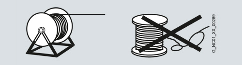
The cables must be removed from the drum without twisting, i.e. the cables must be unwound and must never be lifted over the drum flange in loops.
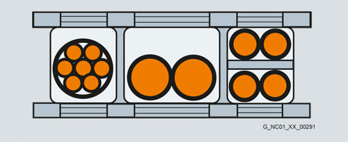
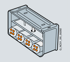
To maximize the service life of the cable carrier and cables, cables in the carrier made from different materials must be separated in the cable carrier by means of spacers. The spacers must be filled evenly to ensure that the position of the cables does not change during operation. The cables should be distributed as symmetrically as possible according to their weights and dimensions. Cables with very different outer diameters should be separated by spacers as well.
When inserting pre-assembled cables into the cable carrier, do not pull at the connector, as this may damage the strain relief or cable clamping.
The cables must not be fixed in the cable carrier. They must be freely movable.
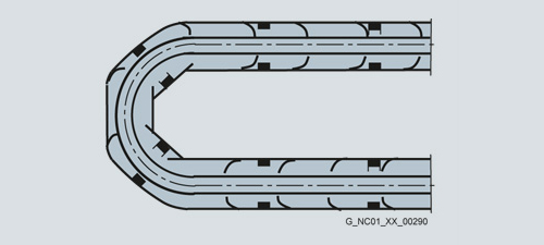
The cables must be able to be moved without applying force in particular in the bending radii of the carrier. The specified minimum bending radii must be adhered to.
The cable fixings must be attached at both ends at an appropriate distance away from the end points of the moving parts in a dead zone.
MOTION-CONNECT cables are tested in a cable carrier. The cables are attached to the moving ends of the cable carrier with strain relief. Strain relief is applied over a wide area of the cable jacket surface without crimping the cable.
Cables must be installed in accordance with the instructions supplied by the cable carrier manufacturer.
Notes:
If, for example, pre-assembled cables are installed in a cable carrier in such a way that the connector would inhibit assembly, pre-assembled cables without assembled connectors can also be supplied (power and signal cables1)). In this case, the contacts of the cables are crimped and the connector enclosure is supplied separately. After installing the cables, the customer assembles the connector enclosure.
In case of vibration load and with horizontal or vertical cable entries, we recommend that the cable is additionally fixed if between the cable strain relief on the cable carrier and the terminal at the motor part of the cable is hanging loose or is not routed. To prevent machine vibrations being transmitted to the connectors, the cable should be fixed at the moving part where the motor is mounted.
1) Not for DRIVE‑CLiQ signal cables.
Symbol | Explanation |
|---|---|
 | Connector with pin contacts |
 | Connector with socket contacts |
 | Exposed core ends |
 | The cable is not included in the scope of supply, it must be provided by the customer. |
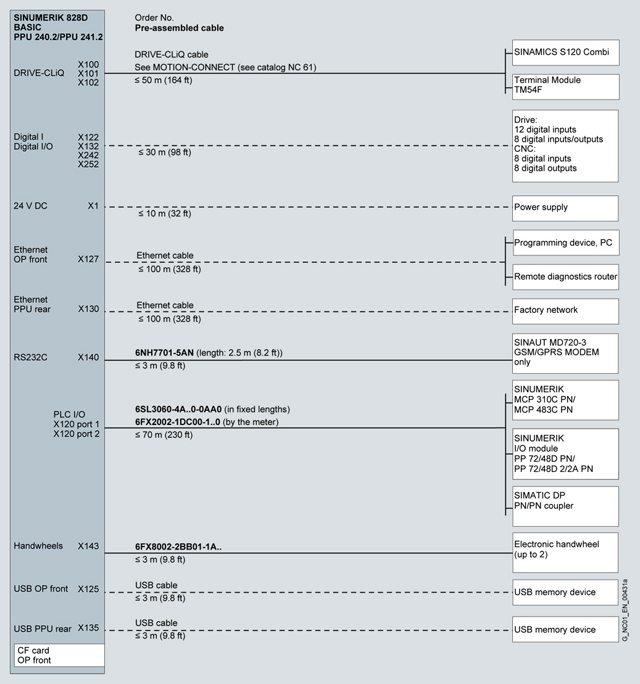
Connection overview of SINUMERIK 828D BASIC T/BASIC M
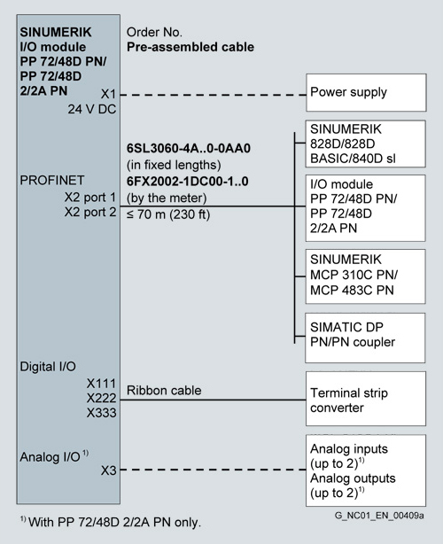
Connection overview of SINUMERIK I/O modules PP 72/48D PN and PP 72/48D 2/2A PN

Connection overview of SINAMICS S120 Combi Power Modules
The current carrying capacity of PVC/PUR-insulated copper cables is specified for installation type C under continuous operating conditions in the table with reference to an ambient air temperature of 40 °C (104 °F). For other ambient temperatures, the values must be corrected using the derating factors in the corresponding table.
Current carrying capacity of cables with copper cores according to EN 60204-1 rms AC 50/60 Hz or DC in A for installation type C | |
|---|---|
Cross-section | Current |
Electronics (one control circuit pair) | |
0.20 | 4.4 |
0.50 | 7.5 |
0.75 | 9.5 |
Power (one symmetrically loaded AC cable) | |
0.75 | 9.8 |
1.00 | 11.7 |
1.50 | 15.2 |
2.50 | 21 |
4 | 28 |
6 | 36 |
Ambient air temperature | Derating factor |
|---|---|
30 (86) | 1.15 |
35 (95) | 1.08 |
40 (104) | 1.00 |
45 (113) | 0.91 |
50 (122) | 0.82 |
55 (131) | 0.71 |
60 (140) | 0.58 |


