
Diaphragm seals of flange design
Diaphragm seals of flange design with flexible capillary | |
Nominal diameter | Nominal pressure |
| PN 10 ... PN 40, PN 100 |
| PN 10 ... PN 40, PN 100 |
| PN 16, PN 40 |
| PN 16, PN 40 |
| Class 150, class 300, class 600, class 1500 |
| Class 150, class 300, class 600 |
| Class 150, class 300, class 400 |
| Class 150, class 300, class 400 |
Sealing face | |
| To EN 1092‑1, form B1 or ASMR B16.5 RF 125 … 250 AA |
| To EN 1092‑1, form B2 or ASME B16.5 RFSF |
Materials | |
| Stainless steel, Mat. No. 1.4404/316L |
| Stainless steel, Mat. No. 1.4404/316L |
| |
| |
| |
| |
Monel 400, mat. No. 2.4360 | |
Hastelloy C276, mat. No. 2.4819 | |
Hastelloy C4, mat. No. 2.4610 | |
Tantalum | |
| Stainless steel 1.4571/316Ti |
| Spiral hose made of stainless steel, mat. No. 1.4301/316L |
Sealing material in the process flanges | |
| Copper |
| Viton |
Maximum pressure | See above and the technical data of the pressure transmitter |
Tube length | Without tube as standard (tube available on request) |
Capillary | |
| Max. 10 m (32.8 ft), longer lengths on request |
| 2 mm (0.079 inch) |
| 150 mm (5.9 inch) |
Filling liquid | |
(for remote seals of sandwich and flange design) | Silicone oil M5 |
Silicone oil M50 | |
High-temperature oil | |
Halocarbon oil (for measuring O2) | |
Food oil (FDA-listed) | |
Glycerine/water (not for use in low-pressure range) | |
Permissible ambient temperature | Dependent on the pressure transmitter and the filling liquid of the remote seal More information can be found in the technical specifications of the pressure transmitters and in the section "Technical data of filling liquid“ in the introduction to the remote seals |
Weight | Approx. 4 kg (8.82 lb) |
Certificates and approvals | |
Classification according to pressure equipment directive (PED 97/23/EC) | For gases of fluid group 1 and liquids of fluid group 1; complies with requirements of article 3, paragraph 3 (sound engineering practice) |
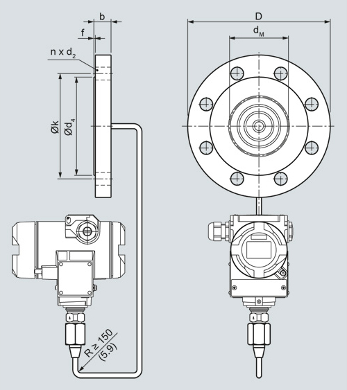
Diaphragm seals of flange design with flexible capillary for connection to SITRANS P pressure transmitters for pressure, dimensions in mm (inch)
Nominal diameter | Nominal pressure | L | D | d2 | d4 | dM | j | k | n |
|---|---|---|---|---|---|---|---|---|---|
mm (inch) | mm (inch) | mm (inch) | mm (inch) | mm (inch) | mm (inch) | mm (inch) | mm (inch) | ||
DN 50 | PN 40 | 20 | 165 | 18 | 102 | 59 | 2 | 125 | 4 |
PN 100 | 28 | 195 | 26 | 102 | 59 | 2 | 145 | 4 | |
DN 80 | PN 40 | 24 | 200 | 18 | 138 | 89 | 2 | 160 | 8 |
PN 100 | 32 | 230 | 26 | 138 | 89 | 2 | 180 | 8 | |
DN 100 | PN 16 | 20 | 220 | 18 | 158 | 89 | 2 | 180 | 8 |
PN 40 | 24 | 235 | 22 | 162 | 89 | 2 | 190 | 8 | |
DN 125 | PN 16 | 22 | 250 | 18 | 188 | 124 | 2 | 210 | 8 |
PN 40 | 26 | 270 | 26 | 188 | 124 | 2 | 220 | 8 |
Nominal diameter | Nominal pressure | L | D | d2 | d4 | dM | j | k | n |
|---|---|---|---|---|---|---|---|---|---|
lb/sq.in. | mm (inch) | mm (inch) | mm (inch) | mm (inch) | mm (inch) | mm (inch) | mm (inch) | ||
(inch) | (inch) | (inch) | (inch) | (inch) | (inch) | (inch) | |||
2 inch | 150 | 19,5 | 150 | 20 | 92 | 59 | 2 | 120,5 | 4 |
(0.77) | (5.80) | (0.79) | (3.62) | (2.32) | (0.08) | (4.74) | |||
300 | 22,7 | 165 | 20 | 92 | 59 | 2 | 127 | 8 | |
(0.89) | (6.50) | (0.79) | (3.62) | (2.32) | (0.08) | (5) | |||
600 | 32,4 | 165 | 20 | 92 | 59 | 2 | 127 | 8 | |
(1.28) | (6.50) | (0.79) | (3.62) | (2.32) | (0.08) | (5) | |||
3 inch | 150 | 24,3 | 190 | 20 | 127 | 89 | 2 | 152,5 | 4 |
(0.96) | (7.48) | (0.79) | (5) | (3.50) | (0.08) | (6) | |||
300 | 29 | 210 | 22 | 127 | 89 | 2 | 168,5 | 8 | |
(1.14) | (8.27) | (0.87) | (5) | (3.50) | (0.08) | (6.63) | |||
400 | 38.8 | 210 | 22 | 127 | 89 | 7 | 168,5 | 8 | |
(1.53) | (8.27) | (0.87) | (5) | (3.50) | (0.28) | (6.63) | |||
4 inch | 150 | 24,3 | 230 | 20 | 158 | 89 | 2 | 190,5 | 4 |
(0.96) | (9.06) | (0.79) | (6.22) | (3.50) | (0.08) | (7.5) | |||
300 | 32,2 | 255 | 22 | 158 | 89 | 2 | 200 | 8 | |
(1.27) | (10.04) | (0.87) | (6.22) | (3.50) | (0.08) | (7.87) | |||
400 | 42 | 255 | 26 | 158 | 89 | 7 | 200 | 8 | |
(1.65) | (10.04) | (1.02) | (6.22) | (3.50) | (0.28) | (7.87) | |||
5 inch | 150 | 24,3 | 255 | 22 | 186 | 124 | 2 | 216 | 4 |
(0.96) | (10.04) | (0.87) | (7.32) | (4.88) | (0.08) | (8,50) | |||
300 | 35,8 | 280 | 22 | 186 | 124 | 2 | 235 | 8 | |
(1.41) | (11.02) | (0.87) | (7.32) | (4.88) | (0.08) | (9.25) | |||
400 | 45,1 | 280 | 26 | 186 | 124 | 7 | 235 | 8 | |
(1.79) | (11.02) | (1.02) | (7.32) | (4.88) | (0.28) | (9.25) |
d: Inside diameter of gasket according to EN 1092-1 / ASME B16.5
dM: Effective diaphragm diameter
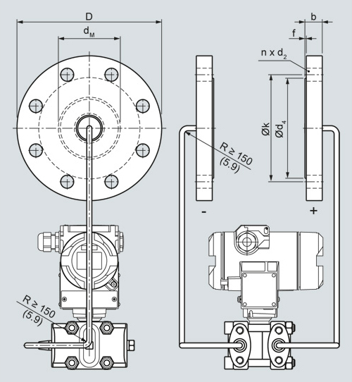
Diaphragm seals of flange design with flexible capillary for connection to SITRANS P pressure transmitters for absolute pressure or for differential pressure and flow, dimensions in mm (inch)
Nominal diameter | Nominal pressure | L | D | d2 | d4 | dM | j | k | n |
|---|---|---|---|---|---|---|---|---|---|
mm (inch) | mm (inch) | mm (inch) | mm (inch) | mm (inch) | mm (inch) | mm (inch) | |||
DN 80 | PN 40 | 24 | 200 | 18 | 138 | 89 | 2 | 160 | 8 |
PN 100 | 32 | 230 | 26 | 138 | 89 | 2 | 180 | 8 | |
DN 100 | PN 16 | 20 | 220 | 18 | 158 | 89 | 2 | 180 | 8 |
PN 40 | 24 | 235 | 22 | 162 | 89 | 2 | 190 | 8 | |
DN 125 | PN 16 | 22 | 250 | 18 | 188 | 124 | 2 | 210 | 8 |
PN 40 | 26 | 270 | 26 | 188 | 124 | 2 | 220 | 8 |
Nominal diameter | Nominal pressure | L | D | d2 | d4 | dM | j | k | n |
|---|---|---|---|---|---|---|---|---|---|
lb/sq.in. | mm (inch) | mm (inch) | mm (inch) | mm (inch) | mm (inch) | mm (inch) | mm (inch) | ||
(inch) | (inch) | (inch) | (inch) | (inch) | (inch) | (inch) | |||
3 inch | 150 | 24,3 | 190 | 20 | 127 | 89 | 2 | 152,5 | 4 |
(0.96) | (7.48) | (0.79) | (5) | (3.50) | (0.08) | (6) | |||
300 | 29 | 210 | 22 | 127 | 89 | 2 | 168,5 | 8 | |
(1.14) | (8.27) | (0.87) | (5) | (3.50) | (0.08) | (6.63) | |||
400 | 38,8 | 210 | 22 | 127 | 89 | 7 | 168,5 | 8 | |
(1.52) | (8.27) | (0.87) | (5) | (3.50) | (0.28) | (6.63) | |||
4 inch | 150 | 24,3 | 230 | 20 | 158 | 89 | 2 | 190,5 | 4 |
(0.96) | (9.06) | (0.79) | (6.22) | (3.50) | (0.08) | (7.5) | |||
300 | 32,2 | 255 | 22 | 158 | 89 | 2 | 200 | 8 | |
(1.27) | (10.04) | (0.87) | (6.22) | (3.50) | (0.08) | (7.87) | |||
400 | 42 | 255 | 26 | 158 | 89 | 7 | 200 | 8 | |
(1.65) | (10.04) | (1.02) | (6.22) | (3.50) | (0.28) | (7.87) | |||
5 inch | 150 | 24,3 | 255 | 22 | 186 | 124 | 2 | 216 | 4 |
(0.96) | (10.04) | (0.87) | (7.32) | (4.88) | (0.08) | (8.50) | |||
300 | 35,8 | 280 | 22 | 186 | 124 | 2 | 235 | 8 | |
(1.41) | (11.02) | (0.87) | (7.32) | (4.88) | (0.08) | (9.25) | |||
400 | 45,1 | 280 | 26 | 186 | 124 | 7 | 235 | 8 | |
(1.79) | (11.02) | (1.02) | (7.32) | (4.88) | (0.28) | (9.25) |
d: Inside diameter of gasket according to EN 1092-1 / ASME B16.5
dM: Effective diaphragm diameter
| Код | Заказной номер | Описание | Вес (кг) | Заказать |
|---|---|---|---|---|
| 71459 | 7MF4920-.....-.. | разделительная мембрана, тип 7mf4920 | 7 | Заказать |
| 117961 | 7MF4921-.....-.. | разделительная мембрана, тип 7mf4921 | 7 | Заказать |
| 117962 | 7MF4923-1....-.B | разделительная мембрана фланцевого исполнения (2 штуки) для датчика дифдавления sitrans p с гибкой каппилярной трубкой | 13 | Заказать |
