In many cases the pressure transmitter and the measured medium have to be physically separated. It is then necessary to use a remote seal.
The remote seals can be used with the following SITRANS P pressure transmitter series:
When configuring your remote seal, be sure to read the information about transmission response, temperature error and response time to be found in the sections "Function" and "Technical data". Only then will the remote seal work to optimum effect.
Remote seal systems should be used if a separation between the measured medium and the measuring instrument is essential or appropriate.
Examples of such cases:
Diaphragm seal
Temperature errors of diaphragm seals when connected to pressure transmitters for pressure, absolute pressure, differential pressure (single-sided) and level
Nominal diameter/design | Diaphragm diameter | Temperature error of remote seal | Temperature error of capillary | Temperature error of process flange/connection spigot | Recommended min. spans (guidance values, observe temperature error) | ||||||
|---|---|---|---|---|---|---|---|---|---|---|---|
mm (inch) | (inch) | mbar/10 K | (psi/ | mbar/ | (psi/ | mbar/10 K | (psi/ | mbar | (psi) | ||
Sandwich design or with flange to EN 1092-1 | DN 50 without tube | 59 | (2.32) | 1,5 | (0.022) | 2 | (0.029) | 2 | (0.029) | 200 | (2.90) |
DN 50 with tube | 48 | (1.89) | 5 | (0.073) | 10 | (0.145) | 10 | (0.145) | 500 | (7.25) | |
DN 80 without tube | 89 | (3.50) | 0,2 | (0.003) | 0,2 | (0.003) | 0,2 | (0.003) | 100 | (1.45) | |
DN 80 with tube | 72 | (2.83) | 1 | (0.015) | 1 | (1.015) | 1 | (1.015) | 250 | (3.63) | |
DN 100 without tube | 89 | (3.50) | 0,2 | (0.003) | 0,4 | (0.006) | 0,4 | (0.006) | 100 | (1.45) | |
DN 100 with tube | 89 | (3.50) | 0,4 | (0.006) | 0,4 | (0.006) | 0,4 | (0.006) | 100 | (1.45) | |
DN 125 without tube | 124 | (4.88) | 0,2 | (0.003) | 0,1 | (0.002) | 0,1 | (0.002) | 20 | (0.29) | |
DN 125 with tube | 124 | (4.88) | 0,2 | (0.003) | 0,1 | (0.002) | 0,1 | (0.002) | 20 | (0.29) | |
Sandwich design or with flange to ASME B16.5 | 2 inch without tube | 59 | (2.32) | 1,5 | (0.022) | 2 | (0.029) | 2 | (0.029) | 200 | (2.90) |
2 inch with tube | 48 | (1.89) | 5 | (0.073) | 10 | (0.145) | 10 | (0.145) | 500 | (7.25) | |
3 inch without tube | 89 | (3.50) | 0,2 | (0.003) | 0,2 | (0.003) | 0,2 | (0.003) | 100 | (1.45) | |
3 inch with tube | 72 | (2.83) | 1 | (0.015) | 1 | (1.015) | 1 | (1.015) | 250 | (3.63) | |
4 inch without tube | 89 | (3.50) | 0,2 | (0.003) | 0,4 | (0.006) | 0,4 | (0.006) | 100 | (1.45) | |
4 inch with tube | 89 | (3.50) | 0,4 | (0.006) | 0,4 | (0.006) | 0,4 | (0.006) | 100 | (1.45) | |
5 inch without tube | 124 | (4.88) | 0,2 | (0.003) | 0,1 | (0.002) | 0,1 | (0.002) | 20 | (0.29) | |
5 inch with tube | 124 | (4.88) | 0,2 | (0.003) | 0,1 | (0.002) | 0,1 | (0.002) | 20 | (0.29) | |
Remote seal with union nut to DIN 11851 | DN 25 | 25 | (0.98) | 20 | (0.290) | 60 | (0.870) | 60 | (0.870) | 6000 | (87) |
DN 32 | 32 | (1.26) | 8 | (0.116) | 25 | (0.363) | 25 | (0.363) | 4000 | (58) | |
DN 40 | 40 | (1.57) | 4 | (0.058) | 10 | (0.145) | 10 | (0.145) | 2000 | (29) | |
DN 50 | 52 | (2.05) | 4 | (0.058) | 5 | (0.073) | 5 | (0.073) | 500 | (7.25) | |
DN 65 | 59 | (2.32) | 3 | (0.044) | 4 | (0.058) | 4 | (0.058) | 500 | (7.25) | |
DN 80 | 72 | (2.83) | 1 | (0.015) | 1 | (0.015) | 1 | (0.015) | 250 | (3.63) | |
Remote seal, screwed gland design | DN 50 | 52 | (2.05) | 4 | (0.058) | 5 | (0.073) | 5 | (0.073) | 500 | (7.25) |
Remote seal with threaded socket to DIN 11851 | DN 25 | 25 | (0.98) | 20 | (0.290) | 60 | (0.870) | 60 | (0.870) | 6000 | (87) |
DN 32 | 32 | (1.26) | 8 | (0.116) | 25 | (0.363) | 25 | (0.363) | 4000 | (58) | |
DN 40 | 40 | (1.57) | 4 | (0.058) | 10 | (0.145) | 10 | (0.145) | 2000 | (29) | |
DN 50 | 52 | (2.05) | 4 | (0.058) | 5 | (0.073) | 5 | (0.073) | 500 | (7.25) | |
DN 65 | 59 | (2.32) | 3 | (0.044) | 4 | (0.058) | 4 | (0.058) | 500 | (7.25) | |
DN 80 | 72 | (2.83) | 1 | (0.015) | 1 | (0.015) | 1 | (0.015) | 250 | (3.63) | |
Clamp connection | 1½ inch | 32 | (1.26) | 8 | (0.116) | 25 | (0.363) | 25 | (0.363) | 4000 | (58) |
2 inch | 40 | (1.57) | 4 | (0.058) | 10 | (0.145) | 10 | (0.145) | 2000 | (29) | |
2½ inch | 59 | (2.32) | 3 | (0.044) | 5 | (0.073) | 5 | (0.073) | 500 | (7.25) | |
3 inch | 72 | (2.83) | 1 | (0.015) | 1 | (0.015) | 1 | (0.015) | 250 | (3.63) | |
Miniature diaphragm seal | G1B | 25 | (0.98) | 20 | (0.290) | 60 | (0.870) | 160 | (2.321) | 6000 | (87) |
G1½B | 40 | (1.57) | 4 | (0.058) | 10 | (0.145) | 15 | (0.218) | 2000 | (29) | |
G2B | 52 | (2.05) | 4 | (0.058) | 5 | (0.073) | 5 | (0.073) | 500 | (7.25) | |
Remarks:
Temperature errors of diaphragm seals with connection to differential pressure transmitters (double-sided)
Nominal diameter/design | Diaphragm diameter | Temperature error of remote seal | Temperature error of capillary | Temperature error of process flange/connection spigot | Recommended min. spans (guidance values, observe temperature error) | ||||||
|---|---|---|---|---|---|---|---|---|---|---|---|
mm (inch) | (inch) | mbar/ | (psi/ | mbar/10 K | (psi/ | mbar/10 K | (psi/ | mbar | (psi) | ||
Sandwich design or with flange to EN 1092-1 | DN 50 without tube | 59 | (2.32) | 0,3 | (0.0043) | 0,3 | (0.0045) | 0,3 | (0.0045) | 250 | (3.626) |
DN 50 with tube | 48 | (1.89) | 1,26 | (0.018) | 1.7 | (0.025) | 1,7 | (0.025) | 250 | (3.626) | |
DN 80 without tube | 89 | (3.50) | 0,05 | (0.001) | 0,05 | (0.001) | 0,05 | (0.0007) | 50 | (0.725) | |
DN 80 with tube | 72 | (2.83) | 0,24 | (0.004) | 0,17 | (0.003) | 0,17 | (0.003) | 100 | (1.45) | |
DN 100 without tube | 89 | (3.50) | 0,05 | (0.001) | 0,07 | (0.001) | 0,07 | (0.001) | 50 | (0.725) | |
DN 100 with tube | 89 | (3.50) | 0,1 | (0.002) | 0,07 | (0.001) | 0,07 | (0.001) | 50 | (0.725) | |
DN 125 without tube | 124 | (4.88) | 0,05 | (0.001) | 0,03 | (0.0004) | 0,03 | (0.0004) | 20 | (0.29) | |
DN 125 with tube | 124 | (4.88) | 0,05 | (0.001) | 0,03 | (0.0004) | 0,03 | (0.0004) | 20 | (0.29) | |
Sandwich design with flange to ASME B16.5 | 2 inch without tube | 59 | (2.32) | 0,3 | (0.0043) | 0,3 | (0.0043) | 0,3 | (0.0045) | 250 | (3.626) |
2 inch with tube | 48 | (1.89) | 1,26 | (0.018) | 1,7 | (0.025) | 1,7 | (0.025) | 250 | (3.626) | |
3 inch without tube | 89 | (3.50) | 0,05 | (0.001) | 0,05 | (0.0007) | 0,05 | (0.0007) | 50 | (0.725) | |
3 inch with tube | 72 | (2.83) | 0,24 | (0.004) | 0,17 | (0.003) | 0,17 | (0.003) | 100 | (1.45) | |
4 inch without tube | 89 | (3.50) | 0,05 | (0.001) | 0,07 | (0.001) | 0,07 | (0.001) | 50 | (0.725) | |
4 inch with tube | 89 | (3.50) | 0,1 | (0.002) | 0,07 | (0.001) | 0,07 | (0.001) | 50 | (0.725) | |
5 inch without tube | 124 | (4.88) | 0,05 | (0.001) | 0,03 | (0.0004) | 0,03 | (0.0004) | 20 | (0.29) | |
5 inch with tube | 124 | (4.88) | 0,05 | (0.001) | 0,03 | (0.0004) | 0,03 | (0.0004) | 20 | (0.29) | |
Remote seal, screwed gland design | DN 50 | 52 | (2.05) | 1 | (0.015) | 0,83 | (0.012) | 0,83 | (0.012) | 250 | -3626 |
Remote seal with union nut to DIN 11851 | DN 50 | 52 | (2.05) | 1 | (0.015) | 0,83 | (0.012) | 0,83 | (0.012) | 250 | (3.626) |
DN 65 | 59 | (2.32) | 0,7 | (0.010) | 0,67 | (0.010) | 0,67 | (0.010) | 250 | (3.626) | |
DN 80 | 72 | (2.83) | 0,24 | (0.004) | 0,17 | (0.003) | 0,17 | (0.003) | 100 | (1.450) | |
Remote seal with threaded socket to DIN 11851 | DN 50 | 52 | (2.05) | 1 | (0.015) | 0,83 | (0.012) | 0,83 | (0.012) | 250 | (3.626) |
DN 65 | 59 | (2.32) | 0,7 | (0.010) | 0,67 | (0.010) | 0,67 | (0.010) | 250 | (3.626) | |
DN 80 | 72 | (2.83) | 0,24 | (0.004) | 0,17 | (0.003) | 0,17 | (0.003) | 100 | (1.450) | |
Clamp connection | 2 inch | 40 | (1.57) | 1 | (0.015) | 2,5 | (0.036) | 2,5 | (0.036) | 2000 | (29.01) |
2½ inch | 59 | (2.32) | 0,7 | (0.010) | 0,67 | (0.010) | 0,67 | (0.010) | 250 | (3.626) | |
3 inch | 72 | (2.83) | 0,24 | (0.004) | 0,17 | (0.003) | 0,17 | (0.003) | 100 | (1.450) | |
Remarks:
Clamp-on seal
Temperature errors of clamp-on seals when connected to pressure transmitters for pressure and absolute pressure, and with single-sided connection to pressure transmitters for differential pressure
Nominal diameter/design | Temperature error of remote seal | Temperature error of capillary | Temperature error of process flange/connection spigot | Recommended min. spans (guidance values, observe temperature error) | ||||
|---|---|---|---|---|---|---|---|---|
mbar/10 K | (psi/10 K) | mbar/10 K | (psi/10 K) | mbar/10 K | (psi/10 K) | mbar | (psi) | |
DN 25 (1 inch) | 6,0 | (0.0870) | 8,5 | (0.123) | 8,5 | (0.123) | 1000 | (14.5) |
DN 40 (1½ inch) | 4,5 | (0.065) | 4,5 | (0.065) | 4,5 | (0.065) | 250 | (3.63) |
DN 50 (2 inch) | 4,0 | (0.058) | 3,0 | (0.044) | 3,0 | (0.044) | 100 | (1.45) |
DN 80 (3 inch) | 9,5 | (0.138) | 5,0 | (0.073) | 5,0 | (0.073) | 100 | (1.45) |
DN 100 (4 inch) | 8,0 | (0.012) | 3,0 | (0.044) | 3,0 | (0.044) | 100 | (1.45) |
Temperature errors of clamp-on seals with double-sided connection to pressure transmitters for differential pressure
Nominal diameter/design | Temperature error of remote seal | Temperature error of capillary | Temperature error of process flange/connection spigot | Recommended min. spans (guidance values, observe temperature error) | ||||
|---|---|---|---|---|---|---|---|---|
mbar/10 K | (psi/10 K) | mbar/10 K | (psi/10 K) | mbar/10 K | (psi/10 K) | mbar | (psi) | |
DN 25 (1 inch) | 2,3 | (0.033) | 1,8 | (0.026) | 1,8 | (0.026) | 1000 | (14.5) |
DN 40 (1½ inch) | 0,8 | (0.012) | 0,3 | (0.004) | 0,3 | (0.004) | 250 | (3.63) |
DN 50 (2 inch) | 0,3 | (0.004) | 0,1 | (0.002) | 0,1 | (0.002) | 100 | (1.45) |
DN 80 (3 inch) | 3,0 | (0.044) | 0,5 | (0.007) | 0,5 | (0.007) | 100 | (1.45) |
DN 100 (4 inch) | 1,0 | (0.015) | 0,1 | (0.002) | 0,1 | (0.002) | 100 | (1.45) |
Remarks:
Calculation of the temperature error
The following equation is used to calculate the temperature error:
dp = (ϑRS – ϑCal) · fRS + (ϑCap – ϑCal) · lCap ·fCap + (ϑTR – ϑCal) · fPF | |
dp | Additional temperature error (mbar) |
ϑRS | Temperature on remote seal diaphragm (generally corresponds to temperature of medium) |
ϑCal | Calibration (reference) temperature (20 °C (68 °F)) |
fDM | Temperature error of remote seal |
ϑCap | Ambient temperature on the capillaries |
lCap | Capillary length |
f Cap | Temperature error of capillaries |
ϑTR | Ambient temperature on pressure transmitter |
f PF | Temperature error of the oil filling in the process flanges of the pressure transmitter |
Example of temperature error calculation
Existing conditions | |
SITRANS P pressure transmitter for differential pressure, 250 mbar, set to 0 ... 100 mbar, with DN 100 remote seal diaphragms without tube, diaphragm made of stainless steel, mat. no. 1.4404/316L | fRS = 0.05 mbar/10 K (0.039 inH2O/10 K) |
Capillary length | lCap = 6 m (19.7 ft) |
Capillaries fitted on both sides | fCap = 0.07 mbar/(10 K · mCap) 0.028 inH2O/(10 K mCap)) |
Filling liquid silicone M5 | fP = 0.07 mbar/10 K (0.028 inH2O/10 K) |
Temperature of medium | ϑRS = 100 °C (212 °F) |
Temperature on the capillaries | ϑCap = 50 °C (122 °F) |
Temperature on pressure transmitter | ϑTR = 50 °C (122 °F) |
Calibration temperature | ϑCal = 20 °C (68 °F) |
Required | |
Additional temperature error of remote seals | dp |
Calculation |
|---|
in mbar |
dp = (100 °C – 20 °C) · 0.05 mbar/10 K + (50 °C – 20 °C) · 6 m · 0.07 mbar/(10 K · m) + (50 °C – 20 °C) · 0.07 mbar/10 K |
dp = 0.8 mbar + 1.26 mbar + 0.21 mbar |
in inH2O: |
dp = (212 °F – 68 °F) · 0.039 inH2O/10 K + (112 °F – 68 °F) · 19.7 ft · 0.028 inH2O/(10 K · 3.28 ft) + (112 °F – 68 °F) · (0.028 inH2O/10 K) |
dp = 0.32 inH2O + 0.51 inH2O + 0.08 inH2O |
Result |
|---|
dp = 2.27 mbar (0.91 inH2O) (corresponds to 2.27 % of set span) |
Note |
The determined temperature error only applies to the error resulting from connection of the remote seal. The transmission response of the respective pressure transmitter is not taken into account here! |
The temperature errors listed in the previous table are based on the use of stainless steel as the diaphragm material. If other diaphragm materials are used, the temperature errors change as follows:
Diaphragm material | Change in temperature error of remote seal |
Increase in values by | |
Stainless steel | See previous tables |
Hastelloy C4, mat. no. 2.4610 | 50 % |
Hastelloy C276, mat. no. 2.4819 | 50 % |
Monel 400, mat. no. 2.4360 | 60 % |
Tantalum | 50 % |
Titanium | 50 % |
PTFE coating on stainless steel diaphragm | 80 % |
ECTFE coating or PFA coating on stainless steel diaphragm | 100 % |
Gold coating on stainless steel diaphragm | 40 % |
The following maximum temperatures of the medium apply depending on the material of the wetted parts:
Material | pabs < 1 bar (402 inH2O) | pabs > 1 bar (402 inH2O) | ||
|---|---|---|---|---|
°C | (°F) | °C | (°F) | |
Stainless steel, 316L | 200 | (392) | 400 | (662) |
PTFE coating | 200 | (392) | 260 | (500) |
ECTFE coating | 100 | (212) | 150 | (302) |
PFA coating | 200 | (392) | 260 | (500) |
Hastelloy C4, mat. no. 2.4610 | 200 | (392) | 260 | (500) |
Hastelloy C276, mat. no. 2.4819 | 200 | (392) | 400 | (662) |
Monel 400, mat. no. 2.4360 | 200 | (392) | 400 | (662) |
Tantalum | 200 | (392) | 300 | (572) |
Nominal diameter | Max. length of capillary | |||||
|---|---|---|---|---|---|---|
Diaphragm seal | Clamp-on seal | |||||
m | (ft) | m | (ft) | |||
DN 25 | (1 inch) | 2,5 | (8.2) | 2,5 | (8.2) | |
DN 32 | (1¼ inch) | 2,5 | (8.2) | 2,5 | (8.2) | |
DN 40 | (1½ inch) | 4 | (13.1) | 6 | (19.7) | |
DN 50 | (2 inch) | 6 | (19.7) | 10 | (32.8) | |
DN 65 | (2½ inch) | 8 | (26.2) | 10 | (32.8) | |
DN 80 | (3 inch) | 10 | (32.8) | 10 | (32.8) | |
DN 100 | (4 inch) | 10 | (32.8) | 10 | (32.8) | |
DN 125 | (5 inch) | 10 | (32.8) | - | - | |
The values listed in the following table are the response times (in seconds per meter of capillary) for a change in pressure which corresponds to the set span.
The listed values must be multiplied by the respective length of the capillary, or with transmitters for differential pressure and flow by the total length of both capillaries.
The response times are independent of the set span within the range of the respective transmitter. The response times are of insignificant importance for spans above 10 bar (145 psi). The response times of the pressure transmitters are not considered in the table.
Filling liquid | Density | Temperature on capillary | Response time in s/m (s/ft) with max. span of pressure transmitter | |||||||
|---|---|---|---|---|---|---|---|---|---|---|
kg/dm3 | (lb/in3) | °C | (°F) | 250 mbar | (101 inH2O) | 600 mbar | (241 inH2O) | 1600 mbar | (643 inH2O) | |
Silicone oil M5 | 0,914 | (0.033) | +60 | (140) | 0,06 | (0.018) | 0,02 | (0.006) | 0,01 | (0.003) |
+20 | (68) | 0,11 | (0.034) | 0,02 | (0.006) | 0,02 | (0.006) | |||
- 20 | (-4) | 0,3 | (0.091) | 0,12 | (0.037) | 0,05 | (0.015) | |||
Silicone oil M50 | 0,966 | (0.035) | +60 | (140) | 0,6 | (0.183) | 0,25 | (0.076) | 0,09 | (0.027) |
+20 | (68) | 0,61 | (0.186) | 0,26 | (0.079) | 0,1 | (0.030) | |||
- 20 | (-4) | 1,69 | (0.515) | 0,71 | (0.216) | 0,27 | (0.082) | |||
High-temperature oil | 1,070 | (0.039) | +60 | (140) | 0,14 | (0.043) | 0,06 | (0.018) | 0,02 | (0.006) |
+20 | (68) | 0,65 | (0.198) | 0,27 | (0.082) | 0,1 | (0.030) | |||
-10 | (14) | 3,96 | (1.207) | 1,65 | (0.503) | 0,62 | (0.189) | |||
Halocarbon oil | 1,968 | (0.071) | +60 | (140) | 0,07 | (0.021) | 0,03 | (0.009) | 0,01 | (0.003) |
+20 | (68) | 0,29 | (0.088) | 0,12 | (0.037) | 0,05 | (0.015) | |||
- 20 | (-4) | 2,88 | (0.878) | 1,2 | (0.366) | 0,45 | (0.137) | |||
Food oil (FDA-listed) | 0,920 | (0.033) | +60 | (140) | 0,75 | (0.229) | 0,33 | (0.101) | 0,17 | (0.052) |
+20 | (68) | 4 | (1.220) | 1,75 | (0.534) | 0,67 | (0.204) | |||
- 20 | (-4) | 20 | (6.100) | 8,5 | (2.593) | 3,25 | (0.991) | |||
Glycerin/water | 1,220 | (0.044) | +60 | (140) | 0,13 | (0.040) | 0,05 | (0.015) | 0,02 | (0.006) |
+20 | (68) | 0,76 | (0.232) | 0,32 | (0.098) | 0,12 | (0.037) | |||
0 | (32) | 9,72 | (2.963) | 4,05 | (1.234) | 1,51 | (0.460) | |||
When selecting the filling liquid, check that it is suitable with respect to the permissible temperature of the medium and the process pressure.
Also check the compatibility of the filling liquid with the measured medium. For example, only physiologically harmless filling liquids may be used in the food industry.
Oxygen and chlorine are special cases of measured medium. The liquid must not react with either of these two media or a leaking remote seal may lead to an explosion or fire.
Filling liquid | Digit in Order No. | Permissible temperature of medium | Density at 20 °C (68 °F) | Viscosity at 20 °C (68 °F) | Coefficient of expansion | ||||||
|---|---|---|---|---|---|---|---|---|---|---|---|
pabs < 1 bar | (pabs < 402 inH2O) | pabs > 1 bar | (pabs > 402 inH2O) | ||||||||
°C | (°F) | °C | (°F) | kg/dm3 | (lb/in3) | m2/s·106 | (ft2/s·106) | 1/°C | (1/°F) | ||
Silicone oil M5 | 1 | -60 ... +80 | (-76 ... +176) | -90 ... +180 | (-130 ... +356) | 0,914 | (0.03) | 4 | (43) | 0,00108 | (0.00060) |
Silicone oil M50 | 2 | -40 ... +150 | (-40 ... +302) | -40 ... +250 | (-40 ... +482) | 0,96 | (0.03) | 50 | (538) | 0,00104 | (0.00058) |
High-temperature oil | 3 | -10 ... +200 | (+14 ... +392) | -10 ... +400 | (+14 ... +752) | 1,07 | (0.04) | 39 | (420) | 0,00080 | (0.00044) |
Halocarbon oil | 4 | -40 ... +80 | (-40 ... +176) | -40 ... +175 | (-40 ... +347) | 1,968 | (0.07) | 14 | (151) | 0,00086 | (0.00048) |
Glycerin/water | 6 | Not possible | Not possible | -10 ... +120 | (+14 ... +248) | 1,22 | (0.04) | 88 | (947) | 0,00050 | (0.00028) |
Food oil (FDA-listed) | 7 | -20 ... +160 | (-4 ... +320) | -20 ... +200 | (-4 ... +392) | 0,92 | (0.03) | 10 | (107) | 0,0008 | (0.00044) |
A remote seal system consists of the following components.
The volume in contact with the measured medium is terminated by a flat embedded elastic diaphragm. Between the diaphragm and the pressure transmitter is the filling liquid.
In many cases, a capillary has to be connected between the remote seal and the pressure transmitter in order e.g. to minimize temperature effects on the latter when hot media are involved.
However, the capillary influences the response time and the temperature response of the complete remote seal system. Two capillaries of equal length must always be used to connect a remote seal to a pressure transmitter for differential pressure.
The remote seal can be optionally equipped with a projecting diaphragm (tube).
Remote seals of sandwich design are fitted with a dummy flange.
Diaphragm seal
With diaphragm seals, the pressure is measured by means of a flat diaphragm which rests in a bed.
The following types of diaphragm seals exist:
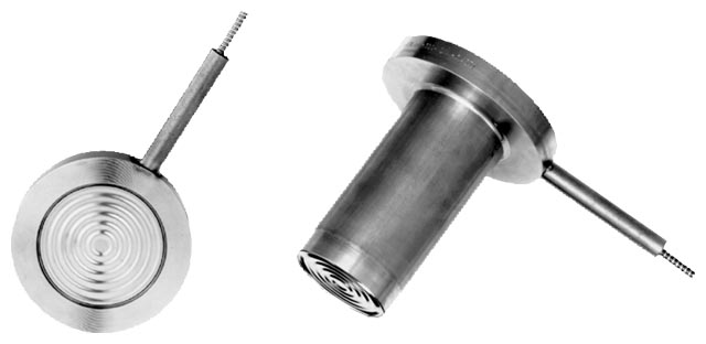
Diaphragm seal of sandwich design without (left) and with a projecting diaphragm (tube)
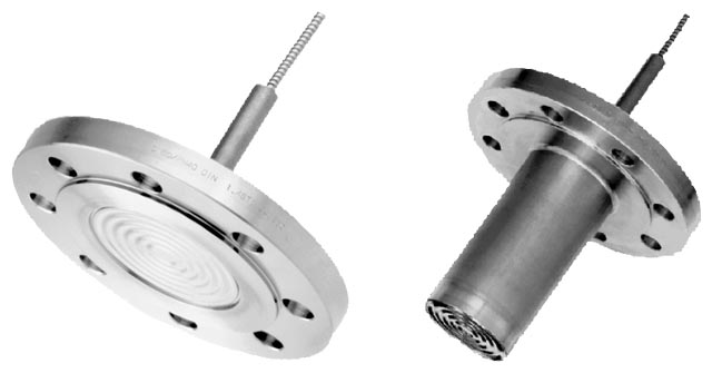
Diaphragm seal of flange design without (left) and with a projecting diaphragm (tube)
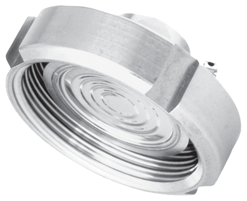
Quick-release diaphragm seal
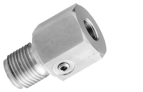
Miniature diaphragm seal with diaphragm flush with front
The quick-release remote seals are primarily used in the food industry. Their design means that the measured medium cannot accumulate in dead volumes. The quick-release clamp present on the remote seal means that quick dismounting is possible for cleaning.
Clamp-on seal
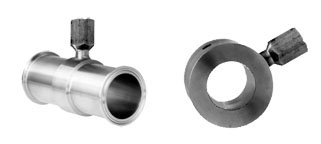
Clamp-on seal with quick-release design (left) and for flange mounting
With clamp-on seals, the pressure is first measured using a cylindrical diaphragm positioned in a pipe, and then transmitted to the pressure transmitter by means of the filling liquid.
The clamp-on seal is a special design for flowing media. It consists of a cylindrical pipe in which a cylindrical diaphragm is embedded. Since it is completely integrated in the process line, no turbulences, dead volumes or other obstructions to the flow occur. Furthermore, the clamp-on seal can be cleaned by a pig.
The following types of clamp-on seals exist:
Note:
The pressure data on the transmitter and the remote seal must be observed with regard to pressure/temperature behavior.
The measured pressure is transferred from the diaphragm to the filling liquid and passes through the capillary to the measuring chamber of the pressure transmitter. The interior of the diaphragm seal and of the capillary, as well as the measuring chamber of the transmitter, are filled gas-free by the filling liquid.
The transmission response of a remote seal is characterized by the following variables:
Temperature error
Temperature errors are caused by the change of volume of the filling liquid due to temperature variations. To select the right remote seal you must calculate the temperature error.
Below you will find an overview of the factors which influence the size of the temperature error, as well as information on how to calculate the temperature error.
The temperature error is dependent on the following variables:
Diaphragm rigidity
The rigidity of the diaphragm is of decisive importance. The bigger the diameter of the diaphragm, the softer the diaphragm and the more sensitively it reacts to temperature-induced changes in volume of the filling liquid.
The result is that small measuring ranges are only possible with large diaphragm diameters.
Other factors apart from diaphragm rigidity which also play a role:
Filling liquid
Every filling liquid reacts to temperature variations with a change of volume. Temperature errors can be minimized by selecting a suitable filling liquid, but the filling liquid must also be appropriate for the temperature limits and operating pressure. Furthermore, the filling liquid must also be physiologically harmless.
Since the filling liquid is present under the diaphragm, in the capillary and under the process flange of the pressure transmitter (or in the connection shank), the temperature error must be calculated separately for each combination.
Note:
When operating in the low-pressure range, also during commissioning, it is recommended to use a vacuum-proof remote seal (see Selection and Ordering data).
An example of a temperature error calculation can be found in the section "Technical Specifications".
Response time
The response time is dependent on the following factors:
The following should be observed to obtain an optimum combination of transmitter and remote seal:
The remote seals listed here are a selection of the most common designs. On account of the large variety of process connections, certain remote seals which are not listed here may be available nevertheless.
Other versions can be:


